In the first part, we will explain what is perpendicularity in GD&T, including its definition, tolerance zone and callout. They are the bases to use perpendicularity correctly in manufacturing.
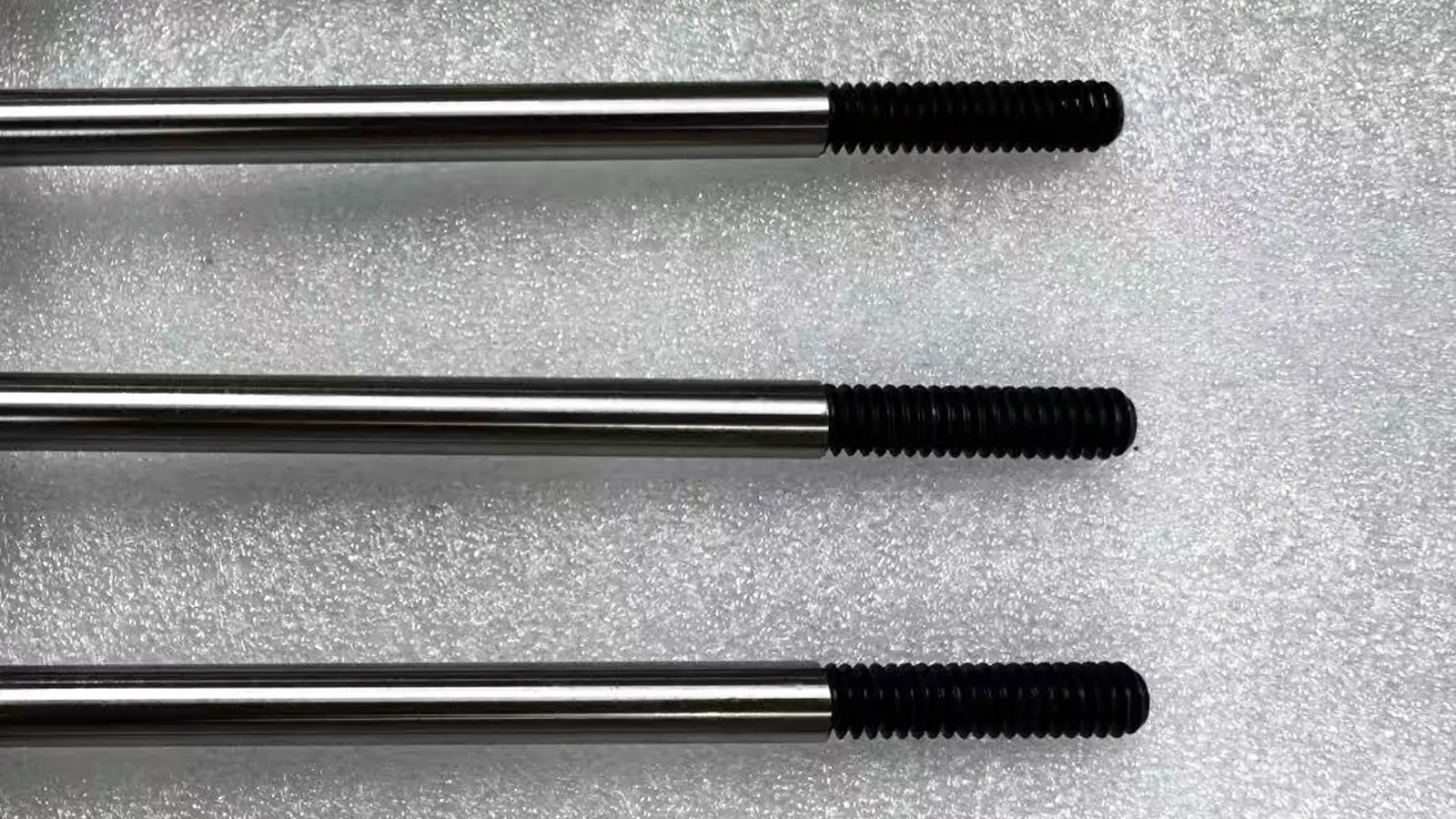
Perpendicularity GD&T is a kind of orientation tolerance to control that the measured elements maintain theoretically perpendicular to the datum elements. Perpendicularity GD&T is used to control the measured surface or axis, keeping 90° with the datum surface or axis.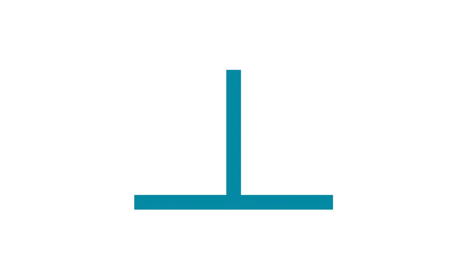
As we all know, it is nearly impossible to keep one element completely perpendicular to another element, though we try hard to achieve it. That is where perpendicularity comes into play.
Perpendicularity tolerance refines a permissible zone where the measured elements can certainly deviate from the perfect perpendicular orientation relative to the datum elements.
Based on the particular controlled elements and specific functions, perpendicularity is divided into two types in GD&T. The are respectively surface perpendicularity and the axis perpendicularity.
For surface perpendicularity, the tolerance zone is comprised with two parallel planes that are both perpendicular to the datum surface. All of the points on the measured surface must lie within the two parallel planes.
Perpendicularity does not directly control the relative angle of the measured surface; instead, it controls the envelope where the measured surface is required to be. Therefore, the tolerance value is the perpendicular distance between the two parallel planes.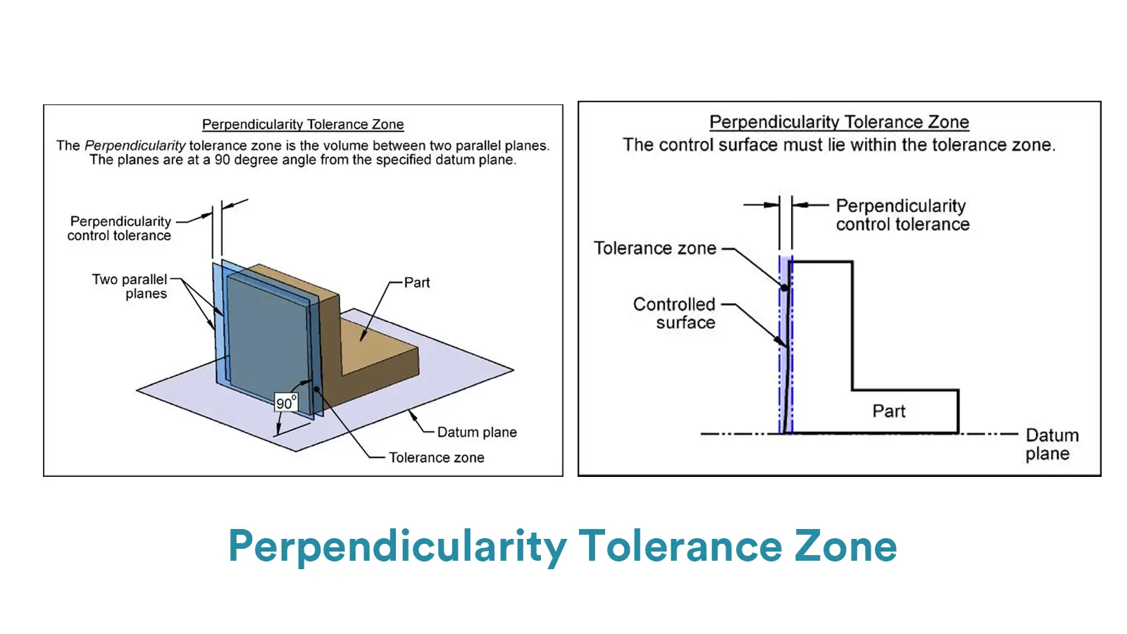
For axis perpendicularity, the tolerance zone is a cylinder whose central axis is theoretically perpendicular to the datum line or surface. All points of the measured axis must lie within the reference cylinder.
And the tolerance value is the diameter of the cylindrical zone. More importantly, as axis perpendicularity is applied to feature of size, it can be used with material modifiers(MMC and LMC). That would give the axis perpendicularity tolerance a bonus tolerance.
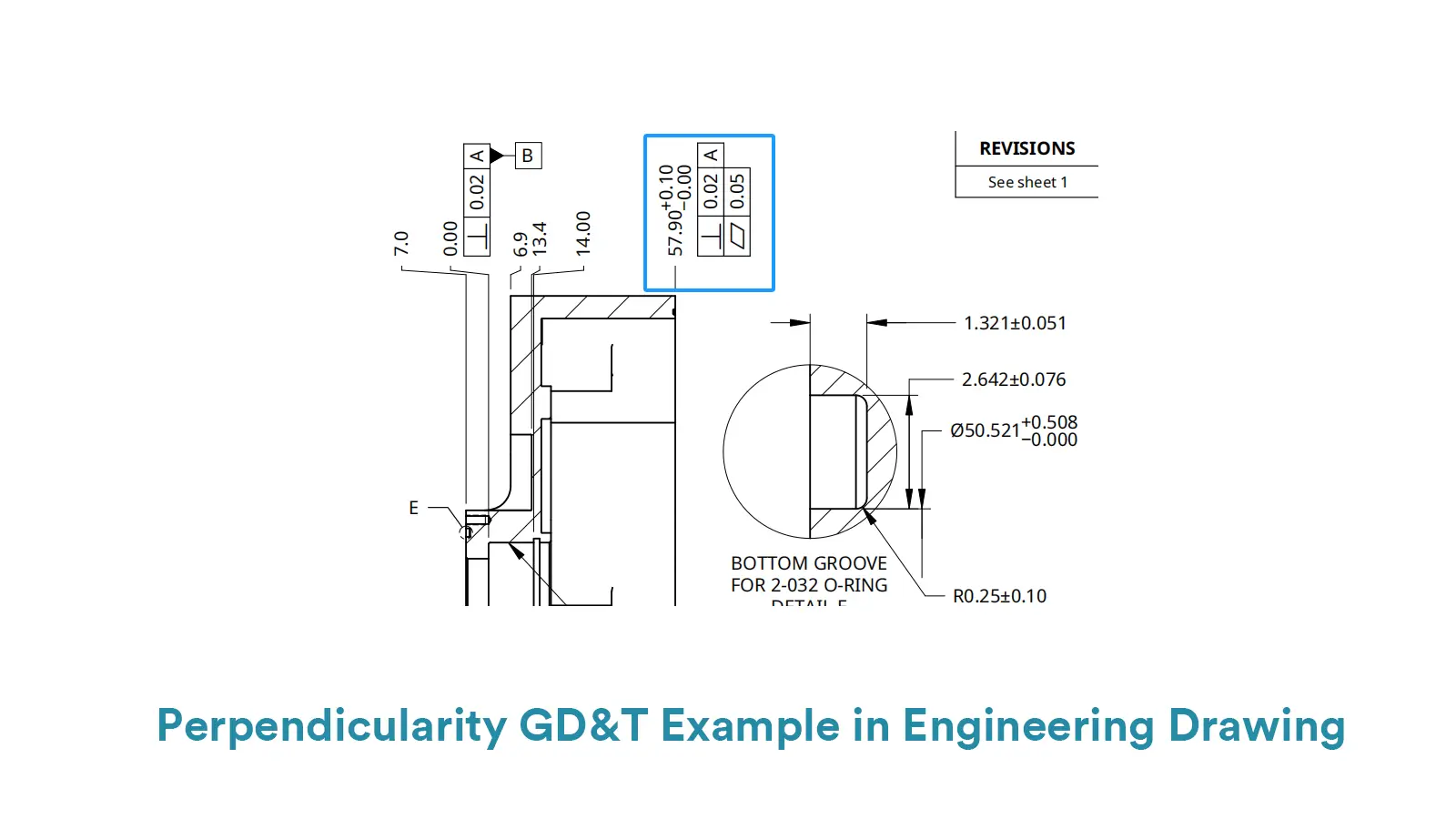
For surface perpendicularity, the feature control frame consists of three factors.
The first one is the symbol of GD&T perpendicularity, which is comprised of two short perpendicular lines, just like an upended “T”.
The second factor is the tolerance value of the surface perpendicularity, which is the shortest distance between the two parallel planes of the zone.
And the third part is the datum symbol. The callout is shown by connecting the feature control frame to the controlled surface or its extension line with a pointing arrow.
For axis perpendicularity, the feature control frame is also composed with three factors.
The first one is the same factor as that of surface perpendicularity, the GD&T symbol of perpendicularity.
While the second part is very different from surface perpendicularity. As the tolerance zone of axis perpendicularity is a cylinder and the tolerance value is the diameter of the cylinder, the symbol of diameter and the value of tolerance are shown in the second part successively.
And the symbol of material modifier( /Ⓛ) follows behind them, being the third element within the second part. The third part is the datum symbol too.
The callout of axis perpendicularity is shown through pointing to the measured axis by a leader arrow connected with feature control frame.
In this part, we will provide comprehensive guides on how to measure perpendicularity GD&T, including the tools, steps as well as their respective advantages and disadvantages.
Square rulers are a kind of simple tool for perpendicularity GD&T measurement. They are suitable for on-site quick inspection and is simple to operate.
What’s more, they have edge in low cost and high efficiency for small components.
However, they seriously rely on skill and experience of operators, and they are disadvantage in limited accuracy(typically ±0.05mm), only suitable for features with low requirement on accuracy. The concrete steps to use this method on perpendicularity measurement are listed below:
Firstly, press the reference edge of the square ruler firmly against the datum surface of the measured component.
Secondly, observe the gap between the other side of the square ruler and the measured surface. And then use a feeler gauge to measure the gap or judge the uniformity of the gap by light leakage.
Thirdly, calculate the deviation of perpendicularity by trigonometry based on the length and height of the gap. If the deviation value is smaller than the tolerance value, the measured feature passes.
Below is an example to show surface perpendicularity measurement using square ruler block and surface gauge.

We have produced that dial gauge with surface plat can be used to measure Parallelism GD&T. It is also a common method to measure perpendicularity GD&T.
This method is suitable to measure component with medium-precision requirement for its higher accuracy(up to ±0.01mm) than square ruler.
But it needs precisely flat plate and stable clamping and is sensitive to environment. The concrete steps to use this method on perpendicularity measurement are listed below:
Firstly, fix the datum surface on the surface plat with precise flatness.
Secondly, fix the dial indicator to a height gauge or a magnetic stand, and place the probe on the measured surface.
Thirdly, move the indicator along the measured surface and record the difference between the max and min readings.
If the difference is smaller than the tolerance value, the measured feature passes.
Perpendicularity measurement using dial gauge photo is shown below.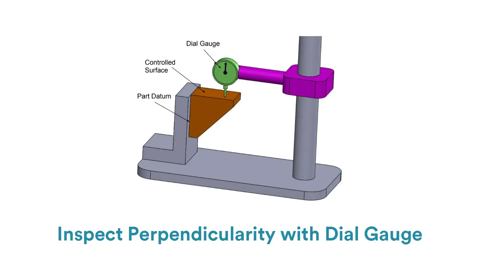
CMMs are automate and versatile machines that can measure components with complex geometries.
And the accuracy is up to ±0.005mm. But the cost of CMMs is high and the measuring speed is slower. The concrete steps to use this method on perpendicularity measurement are listed below:
Firstly, scan the datum surface with the probe to establish a coordinate system.
Secondly, scan the measured surface and collect data of multiple points.
Thirdly, fit planes or axes by CMM software and calculate the perpendicularity deviation. If the outcome is smaller than the tolerance value, the measured feature passes.
Compared with the above methods, autocollimator is a kind of non-contact measurement tool. With ultra-high accuracy, it is suitable for perpendicularity measurement of machine tool guides and large equipment.
However, it is disadvantage in high cost and sensitivity about vibration and temperature. The concrete steps to use this method on perpendicularity measurement are listed below:
Firstly, align the autocollimator to the datum surface until its optical axis is parallel to the datum surface.
Secondly, fix a reflector, like a right-angle prism, on the measured surface.
Thirdly, read angular deviation by autocollimator and convert to perpendicularity deviation. If the value is smaller than the tolerance value, the measured feature passes.
In GD&T, perpendicularity is usually related to flatness and angularity. Here we will explain their similarities and differences.
When it comes to flatness, you may confuse it with surface perpendicularity, since their tolerance zones are similar to some extent. Both of them measure surface deviation between two parallel planes.
But you should know that flatness is a form tolerance while perpendicularity is an orientation tolerance. It essentially causes that perpendicularity needs at least one datum while flatness is independent on datum.
Therefore, though both their tolerance zones are two parallel planes, they are different. Since perpendicularity controls the 90° angle with respect to the datum surface, the two parallel planes must perpendicular to the datum surface first and the angle deviation is controlled indirectly by the distance variation.
While for flatness, it is only concerned with the smoothness of a surface and the flatness deviation is controlled directly by the distance variation.
The relationship between perpendicularity and angularity is much similar to that between parallelism and angularity. It is said that both perpendicularity and parallelism are special forms of angularity.
While angularity is applied to maintain orientation at any specific angle, perpendicularity and parallelism respectively control 90° and 0° with datum feature.
Their tolerance zones are mostly similar to each other, two parallel planes or a cylinder, the only difference is the controlled angle with the datum feature.


Cylindricity is to control the overall deviation of a cylindrical surface from a perfect geometric cylinder.

Parallelism GD&T is to ensure that the reference surface or axis is parallel to the datum surface or axis.

Perpendicularity GD&T is used to control the measured surface or axis, keeping 90° with the datum surface or axis.

GD&T angularity GD&T is used to control a particular angle between the specified feature and the datum feature