In GD&T, the Square symbol (□) addresses these challenges by standardizing drawing semantics, simplifying annotations, and optimizing CNC workflows via single-dimensional labeling that enforces equal side lengths.
In precision manufacturing, product performance relies heavily on precise control of geometric features. Traditional rectangular structure labeling, which uses bidirectional dimensions, often causes interpretation errors, programming complexity, and tolerance issues.
This article comprehensively analyzes the technology from the aspects of GD&T definitions, marking specifications, engineering applications, machining-inspection practices, and related technology comparisons.
Key Takeaways:
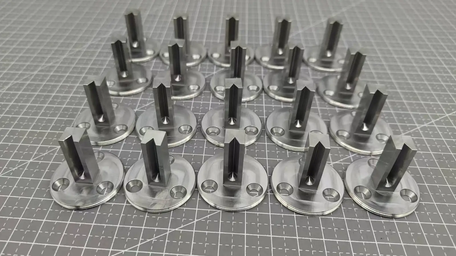
In GD&T, the Square symbol (□) is used to represent a flat feature in three dimensions with four equal and perpendicular sides.
In the GD&T system, the Square symbol (□) serves as a specialized geometric notation on technical drawings, designating features with equal-side square configurations.
Its core function is to replace traditional bi-directional labeling with a single dimension, to enforce the geometric constraint of equal sides, to simplify the complexity of drawings, and to reduce human understanding errors in CNC programming and machining.
Symbol form: represented by a small hollow rectangle “□” whose side length is about 2/3 of the height of the dimension number, and the thickness of the line is the same as that of the dimension number stroke.
Symbol meaning: Replacing multi-dimensional labeling with single dimension labeling, e.g. □10.00 indicates a Square with a side length of 10mm, avoiding repeated labeling of length and width.
Technical nature: By eliminating redundant annotations, the rectangular features in the 2D plane are transformed into special rectangles (Squares) to enhance the standardization of engineering drawings.
Geometric nature: Equal lengths on all sides, 90° perpendicularity of neighboring sides, allowing shape and positional deviations to be defined by tolerance boxes;
Difference with mathematical Square: small geometric errors are allowed in engineering applications, which need to be controlled by both dimensional and shape tolerances, e.g., the actual processing range of a Square with a side length of 10mm can be 9.98~10.02mm, and the perpendicularity error of neighboring sides is ≤0.01mm.
| Technical Dimension | Traditional Bidirectional Dimensioning | Square Symbol Dimensioning |
| Geometric Constraints | No direct symbolic constraints; equal length relies on coincidental dimension values. | Geometric constraints enforced by symbols, granting drawings semantic and legal validity. |
| CNC Programming Efficiency | Requires independent planning of X/Y axis feed logic, increasing path planning complexity. | Can directly call built-in Square cycle commands (e.g., FANUC G51.2 rectangular scaling or MAZAK LATHE SQUARE cycle), reducing code volume by over 30%. |
| Tolerance Transmission | Independent tolerances on two sides may cause cumulative errors. | Single-dimensional tolerance controls all sides, with global accuracy governed by the position tolerance symbol (⌖). |
| Typical Failure Scenarios | Drawing scaling may cause visual inconsistency of X/Y dimensions, leading to rectangular features during machining. | Symbols directly associated with Square features in CAD models to avoid machining errors. |

The standardized annotation of engineering drawings is a prerequisite to ensure manufacturing accuracy. The following section will focus on the basic annotation rules of Square symbols, the datum association method and the specification of composite feature processing, to construct an accurate transformation system from design semantics to processing instructions.
The Square symbol “□” should be strictly placed in front of the size number, forming a standard format of “symbol + size value + unit” to avoid confusion with other geometric features. Labeling components specifically consist of single-feature labeling and multi-feature labeling.
Format: □ + dimension value + tolerance (if the tolerance is symmetric tolerance, “±” should be marked; if it is limit tolerance, the upper and lower deviation should be marked separately).
Example:
Ordinary accuracy: □25.00mm ±0.10mm, indicating a side length of 25mm, allowing ±0.1mm deviation;
Limit tolerance: □30.00mm +0.05/-0.03, indicating a side length range of 29.97~30.05mm.
When there are multiple identical Square features in the drawing, add the quantity before the symbol and connect it with “×”.
For example, 4 × □15.00mm means 4 Squares with side length 15mm.
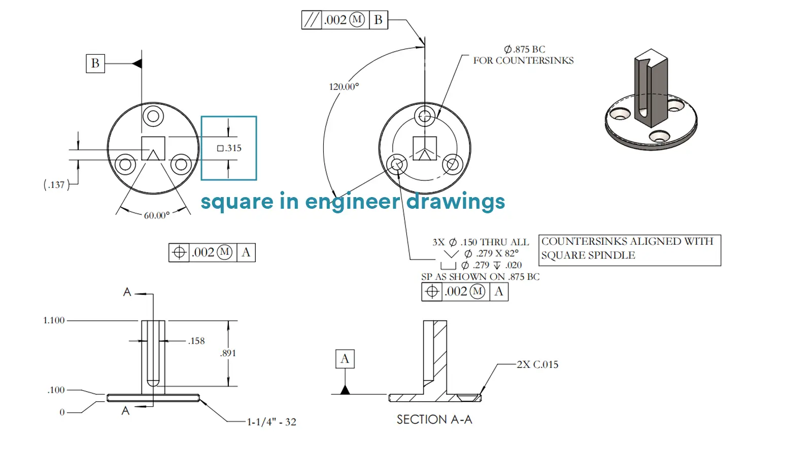
Benchmark positioning annotation: If the Square feature needs to be positioned by a certain datum or axis, a benchmark symbol (such as a letter with a circle) should be added after the dimension.
For example, □40.00mm Ⓐ indicates a Square that is positioned with datum A as a reference. The position of its center or edge in relation to datum A should be clarified by other dimensions.
Composite feature labeling: When the Square feature contains additional structures such as countersunk holes, chamfers, etc., add a description below the dimension line.
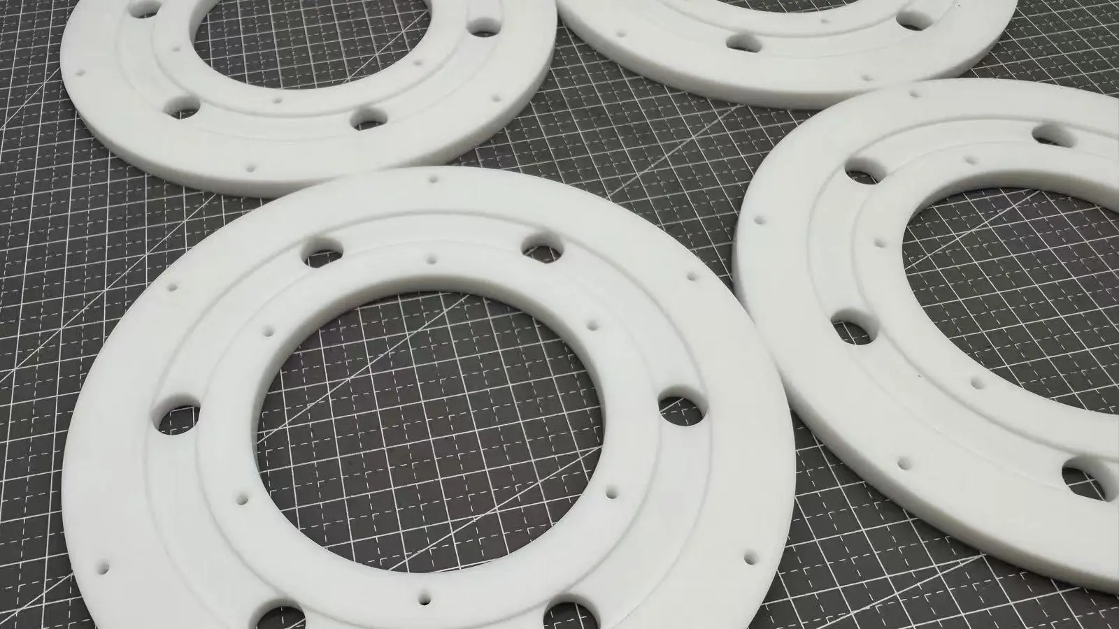
In the precision manufacturing system, Square features have been deeply integrated into the key process links of many industries by virtue of their geometric symmetry and dimensional constraints.
In the following section, we will analyze the typical application scenarios of Square features in the fields of machinery manufacturing, aerospace, semiconductor, etc. from the technical principles of the core features, and reveal the logic of precision control in the details of the assembly technologies.
Function 1: Assembly Accuracy Control
The Square feature ensures the straightness and perpendicularity of the components during assembly through the geometric constraints of equal length on all four sides. For example, the Square design of a machine tool’s guideway slots allows the slider to move accurately in a single direction, avoiding wobbling or stalling caused by inconsistent side lengths.
Function 2: Stress Uniformity
The symmetrical structure of a Square distributes loads evenly to all sides, reducing stress concentrations. For example, the Square connection holes of aerospace equipment balance the forces in all directions during launch vibration through the characteristic of equal length on all four sides, preventing an edge from breaking due to overload.
Function 3: Surface Quality Optimization
Square edges are commonly chamfered or beveled to remove burrs and enhance surface finish.
For example, the Square positioning grooves of semiconductor wafer carriers are chamfered to prevent scratches on silicon wafers and to meet the high-precision requirements of cleanroom environments.
Mechanical Manufacturing
Guideway and Slider Fit: Square guideway grooves (e.g., machine tool tables) are marked by “□” symbols to ensure the straightness of the slider’s motion trajectory, which is commonly used in the linear motion systems of lathes, milling machines, and other equipment.
Mortise and Tenon Structural Joints: Square tenons and mortises are designed to form an interference or clearance fit through tolerance design, such as Square mortises and tenons in wooden furniture, ensuring tightness and stability of the joint through equal length on all four sides.
Aerospace
Structural component connection holes: The Square connection holes of satellite mounts need to meet both dimensional and positional accuracy, and the datum correlation labeling ensures uniform load transfer during the assembly of each component.
Instrument mounting base: The Square mounting base of the instrument inside the spacecraft ensures the stable fixation of the equipment in the weightless environment by controlling the flatness and perpendicularity.
Semiconductor equipment field
Wafer carrier positioning groove: Square positioning groove, such as □80.00mm, the edge is often labeled with inverted round, such as “four corners R0.5mm”, not only to ensure the accuracy of wafer positioning, but also to avoid sharp edges to damage the surface of the silicon wafer.
Chip encapsulation molds: Square encapsulation cavities are processed through high-precision machining, such as slow-feeding wire cutting, to ensure dimensional consistency during chip encapsulation and to prevent encapsulation materials from overflowing or underfilling.
Sealing surface design
For instance, the Square sealing groove of the hydraulic valve block needs to meet the double requirements of “equal length of sides + surface finish”: equal length of the four sides ensures that the seal is uniformly pressurized, and the roughness of the surface is controlled to prevent the seal from being scratched by the rough surface and to avoid leakage of hydraulic oil.
Fastener installation
For instance, when machining square bolt holes on rough surfaces like castings, edge processing via milling or grinding is required to remove casting burrs and unevenness. This ensures a precise fit between the bolt head and surface, averting tilting or stress concentration during installation.
Bearing housing mounting
For instance, the Square mounting surface of the bearing housing needs to be accurately matched with the outer ring of the bearing, and the center should be positioned by datum marking, such as □50.00mm Ⓑ, to prevent running noise and shortened service life caused by tilting of the bearing.
In the process of transforming from design drawings to physical parts, the precise control of machining process and inspection technology is the core of realizing the precision requirements of Square feature. The following section will systematically analyze the key points of the whole machining process, such as tool selection, clamping calibration, etc., and describe the multi-dimensional inspection system from conventional gauges to CMMs.
Tool selection guidelines: Use a 90° end milling cutter for conventional machining, and adopt slow-feeding wire-cutting for high-precision applications.
Clamping and calibration: calibrate the workpiece datum surface by means of a ruler or micrometer to ensure that the workpiece is parallel to the machine axes;
Machining steps: rough milling to leave a margin, then finish milling in several passes, and finally milling along the contour to ensure the surface finish clockwise.
Edge length detection: ordinary precision with vernier calipers or micrometers, high precision with CMM;
Perpendicularity inspection: Use a right-angle ruler with a plug gauge for general measurements, or a laser interferometer for high-precision scenarios.
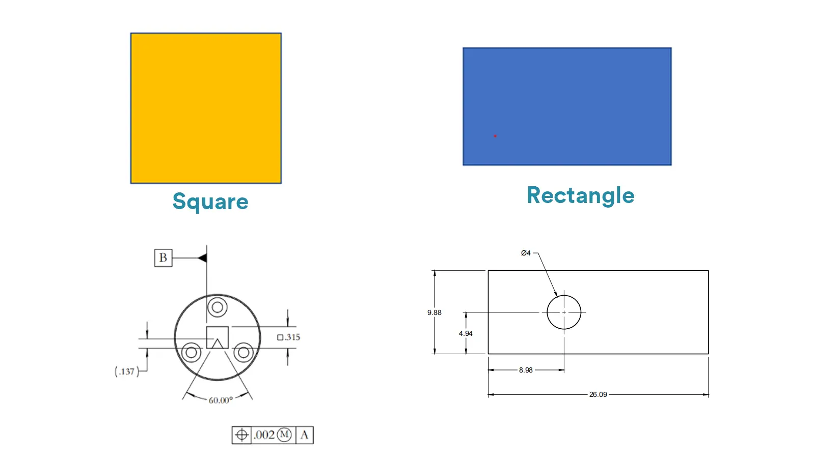
In engineering practice, clarifying the technical differences between Square and similar features is the key to avoiding design misunderstanding and processing errors. In the following section, we will systematically analyze Square vs. rectangle, Square symbols and Square units from the dimensions of geometric definition, labeling rules and application scenarios.
A square is basically a special kind of rectangle — it’s got four sides that are all the same length and four perfect right angles. A regular rectangle also has four right angles, but the sides don’t have to be the same length — the opposite sides just need to match.
A Square is used for symmetric fit structures by controlling the equal length of the four sides through the “□” symbol and a single dimension; a rectangle needs to be labeled with the length and width, and is suitable for asymmetric structures.
“□” denotes a geometric feature (e.g. □10mm) and “²” denotes a unit of area (e.g. 10mm²), confusion can lead to machining errors.
ASME standard allows “□” or ‘SQ’ abbreviation, while ISO only uses “□”; the order of tolerance marking is different, and cross-standard applications need to indicate the following specifications in the title column.
Tolerances are marked in a different order, and cross-standard applications should be indicated in the title column of the specification to be followed.
Missing symbols: “□” must be used to mark the Square to avoid mistakenly machining it as a rectangle;
Conflicting tolerances: Perpendicularity tolerance should be controlled within 1/2 of the tolerance zone of the dimension;
Errors in datums: Choose stable support surfaces as the datums to ensure that the measurements are in line with the assemblies.
The Square symbol lets you show that all four sides are the same length with just one dimension, which is way simpler than using separate length and width.
It updates the old rectangle labeling method, makes drawings cleaner, and works well across different industries like aerospace, machining, and semiconductors.
The square symbol also helps reduce machining errors and makes CNC programming easier by cutting down on complexity.
Since the design, production, and inspection steps all follow the same rules, it keeps everything accurate and consistent — pushing precision manufacturing toward smarter, more digital workflows.

Lucas is a technical writer at ECOREPRAP. He has eight years of CNC programming and operating experience, including five-axis programming. He’s a lifelong learner who loves sharing his expertise.

5-Axis CNC machining is a manufacturing process that uses computer numerical control systems to operate 5-axis CNC machines capable of moving a cutting tool or a workpiece along five distinct axes simultaneously.

China is the best country for CNC machining service considering cost, precision, logistic and other factors. Statistical data suggests that China emerges as the premier destination for CNC machining.

Selecting the right prototype manufacturing supplier in China is a critical decision that can significantly impact the success of your product development project.

Machining tolerances stand for the precision of manufacturing processes and products. The lower the values of machining tolerances are, the higher the accuracy level would be.