In fact, the true position GD&T is better to be defined as GD&T position tolerance, for “true position” actually refers to the exact location determined by basic dimensions or other nominal values.
However, since True Position is the more commonly used term when people are looking for the position tolerance, we will mainly use true position GD&T as a term referring to the GD&T position tolerance in this article. And in this part, we will explain the true position definition and its tolerance zone.
True position GD&T is one of the position symbols in GD&T that is used to control the positional accuracy of a feature of size, such as a hole, shaft or slot, with respect to the datum coordinate system.
In short, true position GD&T confines the total permissible deviation of a feature’s actual position from its ideally “true” position.
As a powerful positional tolerance, true position GD&T can be applied to any feature of size. By controlling the central elements of theses size features, the position is be in command.
In other word, true position GD&T defines the acceptable area where the feature of size’s center or central axis can vary from its ideally accurate position.
The GD&T true position tolerance zone has two types, the cylinder tolerance zone and the square tolerance zone.
Actually, thought the GD&T true position can be use to control any feature’s position, it is mostly applied to control circular or cylindrical features. So, the cylindrical tolerance zone is the more common one in engineering and manufacturing.
When used to control the actual position of a circular feature, the tolerance zone of true position GD&T is a cylinder whose central axis stands for the ideal position of the measured center element of feature of size.
The cylindrical area confines the permissible zone where the actual position must lie within. And the tolerance value is the diameter of the cylinder zone. But note that the permissible deviation is only half the diameter. The measured position can vary from 360° in 3-Dimension and distances of all direction are the same.
Another tolerance zone of true position GD&T is the square tolerance zone. It occurs usually when the measured feature is non-circular feature and the position is confined by the distances from X axis and Y axis which refers to the datum direction.
In such a case, the tolerance zone would be a square whose side length is the tolerance value. And the measured position can vary from X axis and Y axis the half of tolerance value. This means is same as the traditional leaner tolerancing.
Note that the cylinder tolerance zone is much more commonly used to control position. Since the corners’ distances from the square’s center are further than that of the sides, which would remove over 57% of the tolerance zone and then make the tolerance tighter.
The feature control frame of true position GD&T consists of three blocks.
The first block contains the geometric characteristic symbol of GD&T position. It is a circle with a crosshair at the center and stretching out the circle(⌖).
The second block contains tolerancing information. If the symbol of diameter is within the block before the tolerance value, it means that the tolerance zone of the GD&T positional tolerance is a cylinder.
While if there is no diametric symbol in the block, it means that the tolerance zone is the square one. The former situation appears much more common.
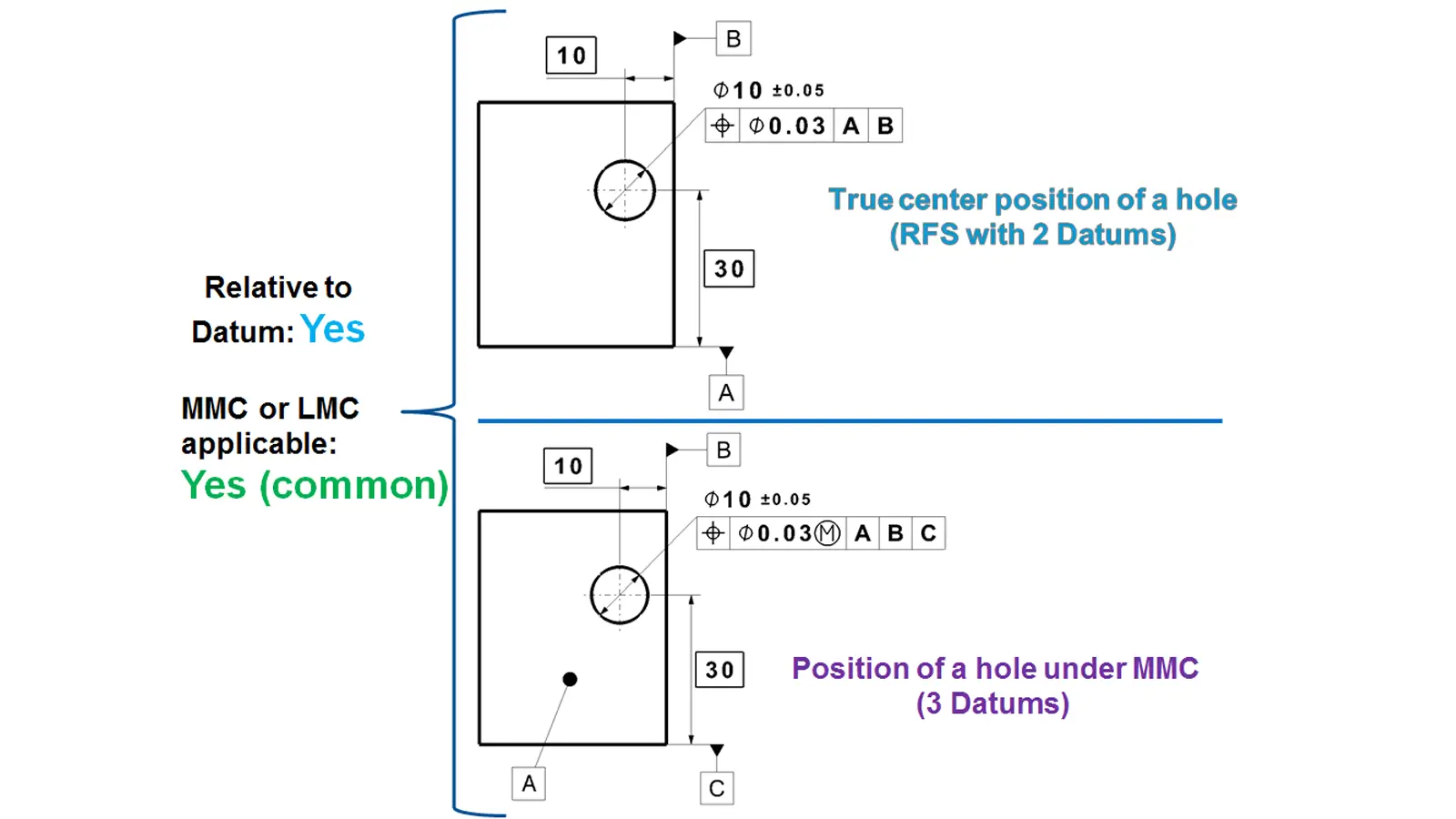
And position tolerance GD&T can be used with modifiers. Therefore, the symbol of MMC(M) and LMC(L) might present in the block behind the tolerance value. But note that it is usually used at RFS(Regardless of Feature Size) condition.
The third block contains the symbol of datums. As the true position should be located through three reference direction in most situation, symbols of A, B and C might all appear in the block.
And then the feature control frame would be connected with a leader arrow which points to the edge line of the controlled feature.
In this part, we will explain the application of true position GD&T, including how to read it and calculate it under different conditions. Here we will take an GD&T positional tolerance example for explanation.
As the above picture shown, it is a block with a hole. The feature control frame of the hole’s position tolerance is applied to the basic dimension 20 for the hole’s diameter with +/-0.2 tolerance.
The primary, secondary and tertiary datum are respectively three mutually perpendicular surfaces of the block. The example above is common on datum choose.
Usually, we would take the bottom surface of the block as the primary datum(A), which would specify that the central axis of the hole must be perpendicular to the bottom surface.
Then we would select the left and front surface as the secondary(B) and tertiary(C) datum respectively, which controls the position’s distance from them. In the above distant, the true position is located by the basic dimensions shown in the boxes. They are particularly 20 and 25 with respect to the datum B and C.
And the tolerance zone is a cylinder of 0.1 diameter. It means that the position of the actual hole, also the hole’s center, must lie within a circle of 0.1 diameter whose center is the true position(theoretically ideal position) of the ideal hole. Then with the depth in consideration, the central axis of the actual hole must lie within the cylinder of 0.1 diameter.
Below is the GD&T true position formula:

The Measured X and Y above are the actual distances of the hole’s position from the datum B and C. And the True X and Y are the distances of the hole’s theoretical position from datum B and C, also the basic dimension shown beside the datum surfaces.
For the above distant,

If the final value is smaller than 0.1 or is exactly 0.1, the measured feature passes.
In addition, when the GD&T true position tolerance is used under Maximum Material Condition(MMC) or Least Material Condition(LMC), the actually acceptable tolerance would depend on the actual size of the feature. It means that the GD&T true position tolerance would achieve bonus tolerance.
When GD&T true position is used with MMC, the actual permissible tolerance value would be “Indicated Tolerance Value +∣Actual Dimension – MMC Dimension∣.
When GD&T true position is used with LMC, the actual permissible tolerance value would be “Indicated Tolerance Value + ∣LMC Dimension – Actual Dimension∣.


GD&T profile of a line is to control the deviation of any actual linear element on surfaces, like straight lines, curved lines or lines on cross-section planes from their exactly ideal profile.

Symmetry controls that the Median Plane of a non-rotating feature must be aligned with the Datum Center Plane. It has been removed from the standard GD&T toolbox.

Concentricity is a position tolerance that measures the degree to which the center points of circular features (cylinders, cones, spheres) coincide relative to a shared datum axis or point.

True position GD&T is one of the position symbols in GD&T that is used to control the positional accuracy of a feature of size, such as a hole, shaft or slot, with respect to the datum coordinate system.