First of all, we should know about what is flatness in GD&T. This section will explain the definition and the symbol of flatness as well as the tolerance zone of flatness.
As one of the most useful engineering tolerancing symbols in GD&T, flatness controls the applicable form deviation from the true surface to the ideally designed surface. Flatness is the acceptable deviation of the true surface confined by two theoretical parallel surfaces.
And note that flatness is independent to datums and other GD&T symbols.
In GD&T, the symbol of flatness is generally indicated by a parallelogram. Below is a typical example of GD&T symbol for flatness: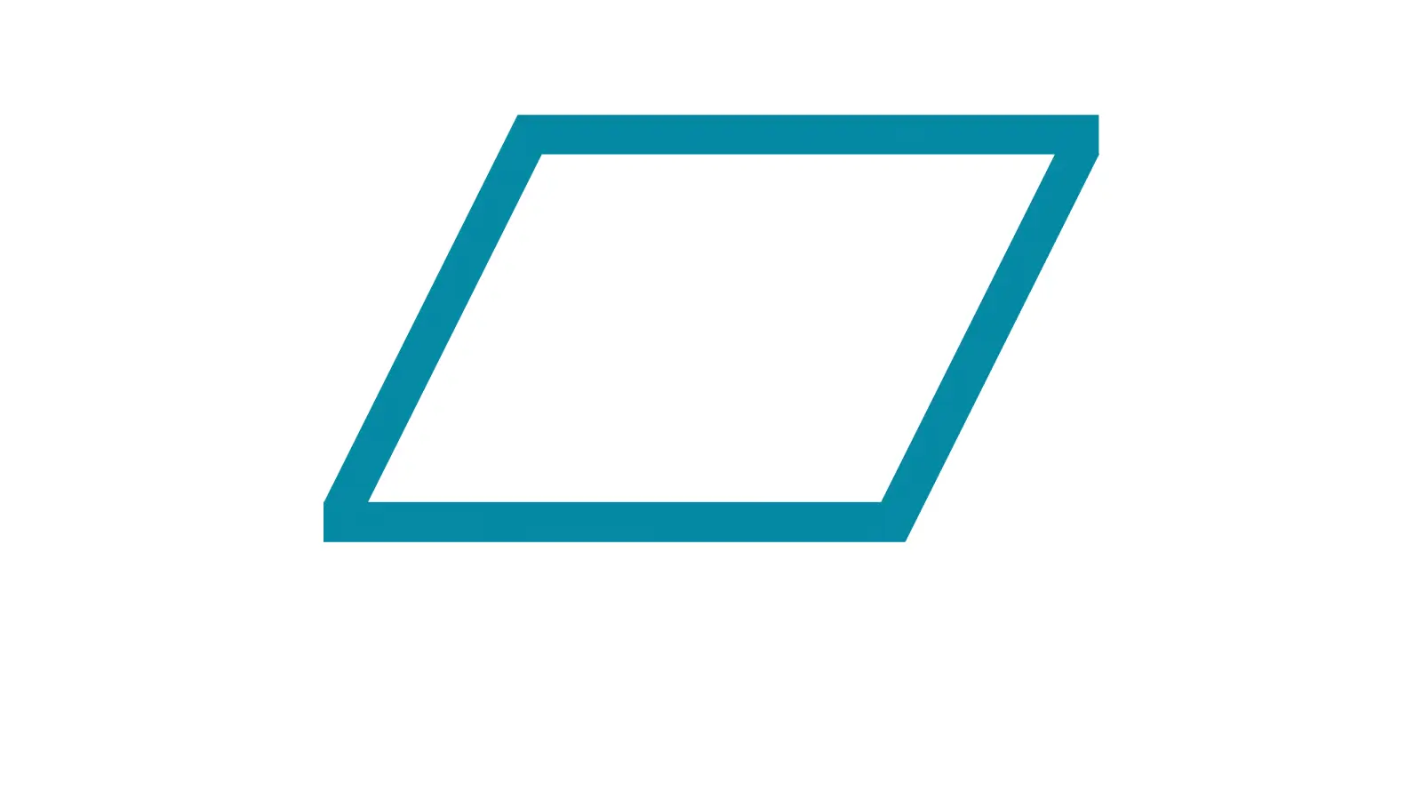
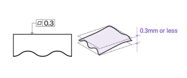
The tolerance zone of flatness is a 3D restraint. It confines that all points on the manufactured surface must lie within two parallel surfaces above and below the referenced surface. And the flatness tolerance value is the distance of the two parallel surfaces. Below is an example of flatness tolerance:
As flatness is independent from datum and any other geometric symbols, the feature control frame of flatness is typically comprised of simply two elements.
The first block contains the geometric characteristic symbol for flatness and the second one indicates the tolerance value, with modifier in some cases. Here we will introduce how to show flatness on engineering drawings in different applications.
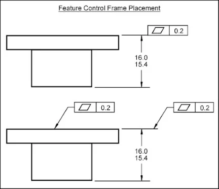
It is said that flatness is mostly used on a surface. The tolerance zone consists of two parallel surfaces. In such a case, the flatness callout would directly point to the flat surface with a leader line, or directly connect to the extension line from the referenced surface.
The example of flatness callout in such a case is as follows:
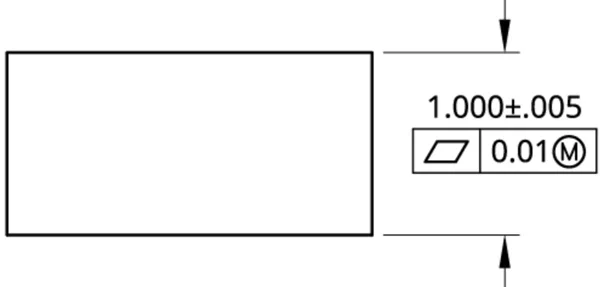
When applied to a feature of size, flatness is often related to DMP(Derived Median Plane) in GD&T. In such cases, it is the virtual DMP of the referenced feature of size that is controlled by flatness tolerance.
What’s more, the MMC(Maximum Material Condition) and the LMC(Least Material Condition) are generally applied under such circumstance. The example is shown below:
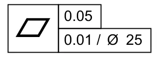
In some cases, the local flatness is needed and indicated in the feature control frame with overall surface flatness. It occurs when the surface is too huge or difficult to control, or when the functional element requires more accuracy flatness control.
Usually, the tolerance of local flatness would be indicated close to the entire surface flatness with confined area. The example callout is as follows:
The main methods to measure flatness include height gauge, surface plate and coordinate measuring machine. They are applied to measure flatness based on different level of accuracy and respective advantages.
Height gauges are commonly used to measure flatness. Below are steps to measure the flatness with height gauge.
First, the bottom surface of the part would be placed on three columns with equal height.
Second, through adjusting the heights of these columns, a perfectly flat plane would be simulated out.
Finally, the deviation would be monitored during the process when the indicator of the height gauge slides across the entire surface. The part passes only if the needle deviation remains within the flatness tolerance.

Height gauges are generally used to measure plane features with middle or small size, and are suitable for accuracy level of 0.01-0.05mm. The advantages of height gauges include that they are easy to operate and cost less to some extent.
However, they are not applicable when extremely higher accuracy level is required and need too much time to measure, not suitable for large quantity of production.
Surface plate are also one of the most commonly used methods to measure flatness. A surface plate is usually made by an extremely flat granite for good thermal stability and damping. Below are steps to use surface plate to measure flatness.
First, the measured surface would be placed on the surface plate.

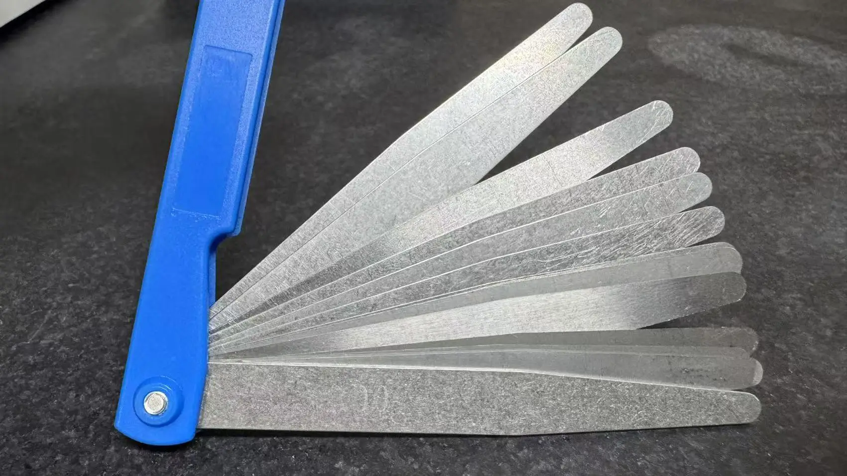
Second, a feeler gauge or a dial indicator would be used to measure the gap between the measured surface and the surface plate.

Additionally, bluing can also be used with surface plate.
This method can ensure higher accuracy than height gauges if the granite has good quality.
But note that it is supposed to regularly recalibrate the surface plate in case it has suffered severe wear.
Coordinate Measuring Machines are the most accurate equipment for flatness measuring in GD&T.
Compared to the above two methods, they are automated, precise, and independent from plane orientation. In addition, CMMs are compatible with CAD software, offering more flexibility and convenience during performing quality inspect.
A CMM works by sampling several points of the surface to collect the cloud statistics of these points. The number of point samples depends on the size of the part and the required accuracy level.
Then, the CMM software evaluates the cloud points to inspect the flatness tolerance.
The two commonly used algorithms of the CMM software are Least Squares Method and Minimum Zon Cylinder. CMMs stand out for its high measuring accuracy and good feasibility for flexible curved surface inspect. But the high cost should be considered too.
It is known that flatness, straightness and parallelism are all important symbols in GD&T. However, many people may confuse about the difference between the flatness and straightness as well as that between the flatness and parallelism.
Flatness controls the form deviation of an entire plane surface while straightness restrains the bending or curving degree of a line. In general, as straightness is typically used in 2D dimension, flatness can be seen as the 3D equivalent of the surface straightness control.
But straightness can also be applied in 3D dimension. At this moment, it is used to control the axis of a feature of size, and the tolerance zone would be a cylinder area instead of the zone between two parallel lines.
Flatness is typically used to control fixture base plates in machining and sealing interfaces to prevent leaks etc. While straightness is typically used to control cutting toll edges or guide rail edges etc.
Flatness controls the form deviation of a single true surface itself while parallelism controls the parallel deviation from the measured surface or axis to the datum surface or axis.
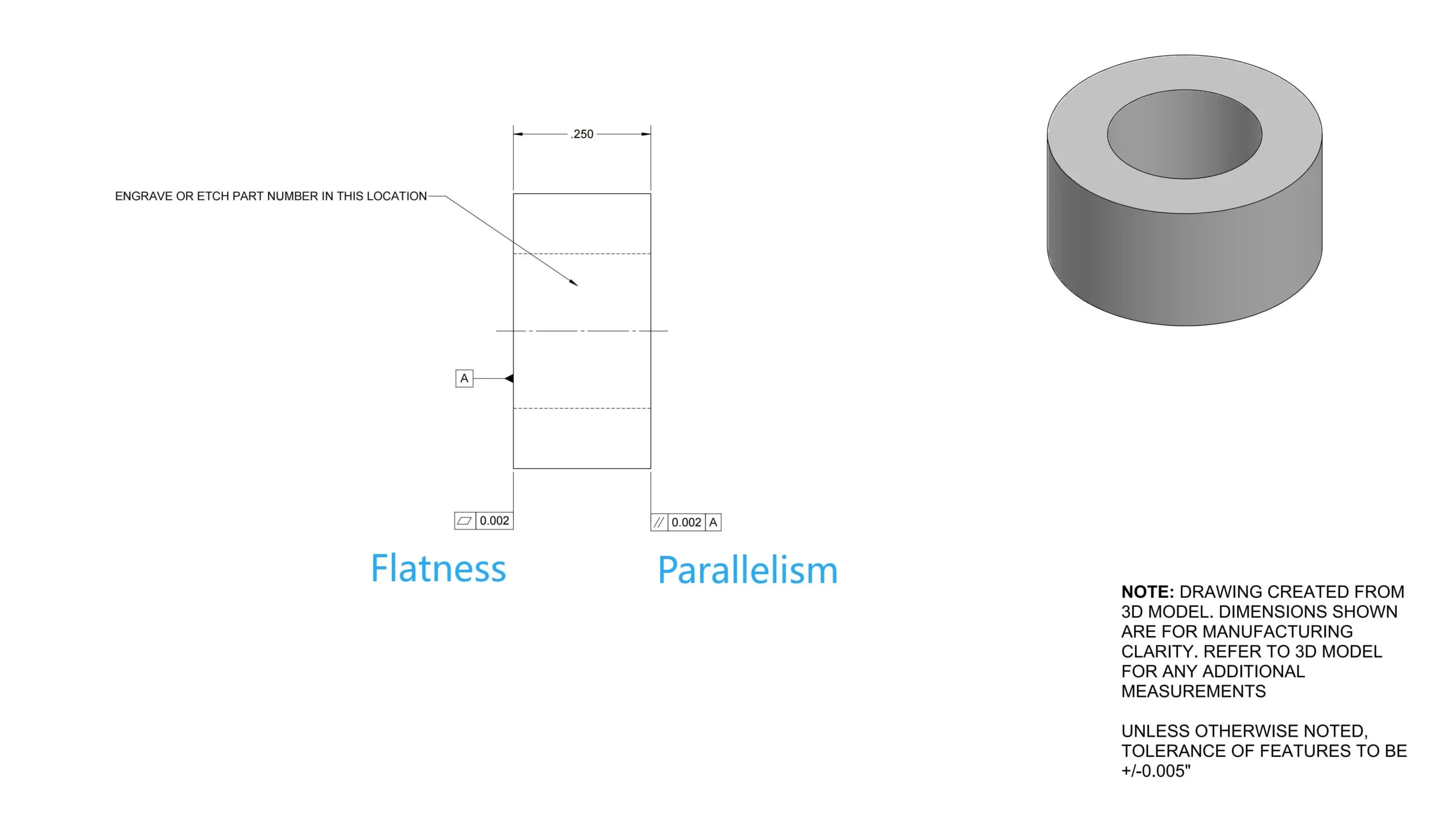
That is to say, flatness is a kind of form tolerance that only focuses on whether the measured surface itself is flat or not. But straightness is a kind of direction tolerance to ensure that the measured feature keeps parallel to the datum.
Flatness is independent to datums and other GD&T symbols while parallelism is a relative tolerance and the datum (such as datum plane A) must be clearly marked.