Consider these to be additional considerations. The above-mentioned are some of the best industry practices helping to make CNC designs way more reasonable.
This indication lets a manufacturer know how precisely the produced part must match the given specification. These also help you to predict how tightly distinct components that form a larger part will enter each other. Tighter tolerance = higher accuracy and vice versa.
Most CNC machines and their tooling already have an optimal accuracy set. There is no trouble if you are fine with looser tolerances than a manufacturer offers by default. But you should think twice before requesting the dimensions to be almost exact. This will highly increase costs and reduce the speed of manufacturing. Some extremely tight tolerances are impossible to produce.
Remember, there is no point in requesting close matches for inessential features of the model and all the prototypes.
Recommendation: stick to ± 0.025 mm., which is standard.
Related Post: CNC Machining Tolerances, the Complete Guide in 2022

The issue is that mill tools have a strictly limited cutting length. The small depth-to-width ratio is explained by tool deflection, nuances of chip evacuation, and vibration effects.
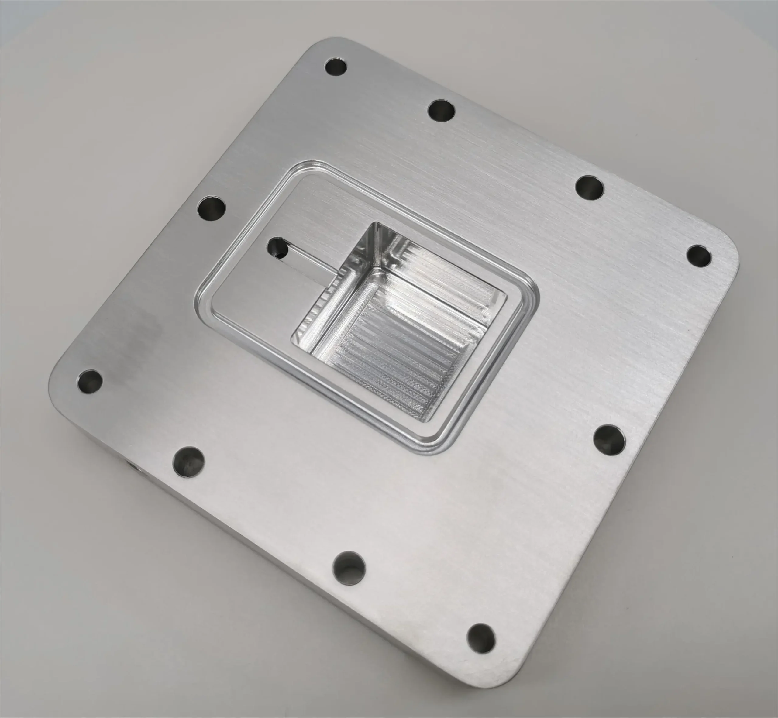
Cavities with a depth exceeding six times the tool diameter and technically deep. The maximal possible aspect ratio is 30:1 which can be achieved by using a specialized 1-inch diameter end mill.
Recommendation: cavity depth should not exceed 4 times cavity width.
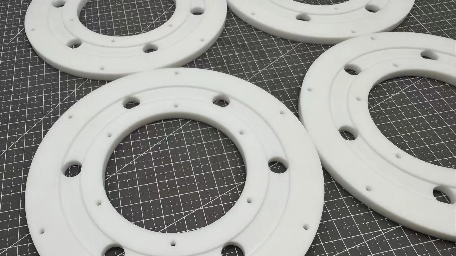
As a rule – the thinner the wall is the less stiffness of the material is. It increases the effects of vibration and lowers possible accuracy. Besides, plastic is prone to warping because of residual stress and increased surface temperature. Not to mention that thin walls, especially higher ones, can be easily damaged which reduces total yield.
So, it’s highly advised to stick to feasible values of wall thicknesses and keep them consistent throughout the design.
Recommendation: minimal thickness should be 0.8 mm. for parts from metal and 1.5 mm. for parts from plastic.
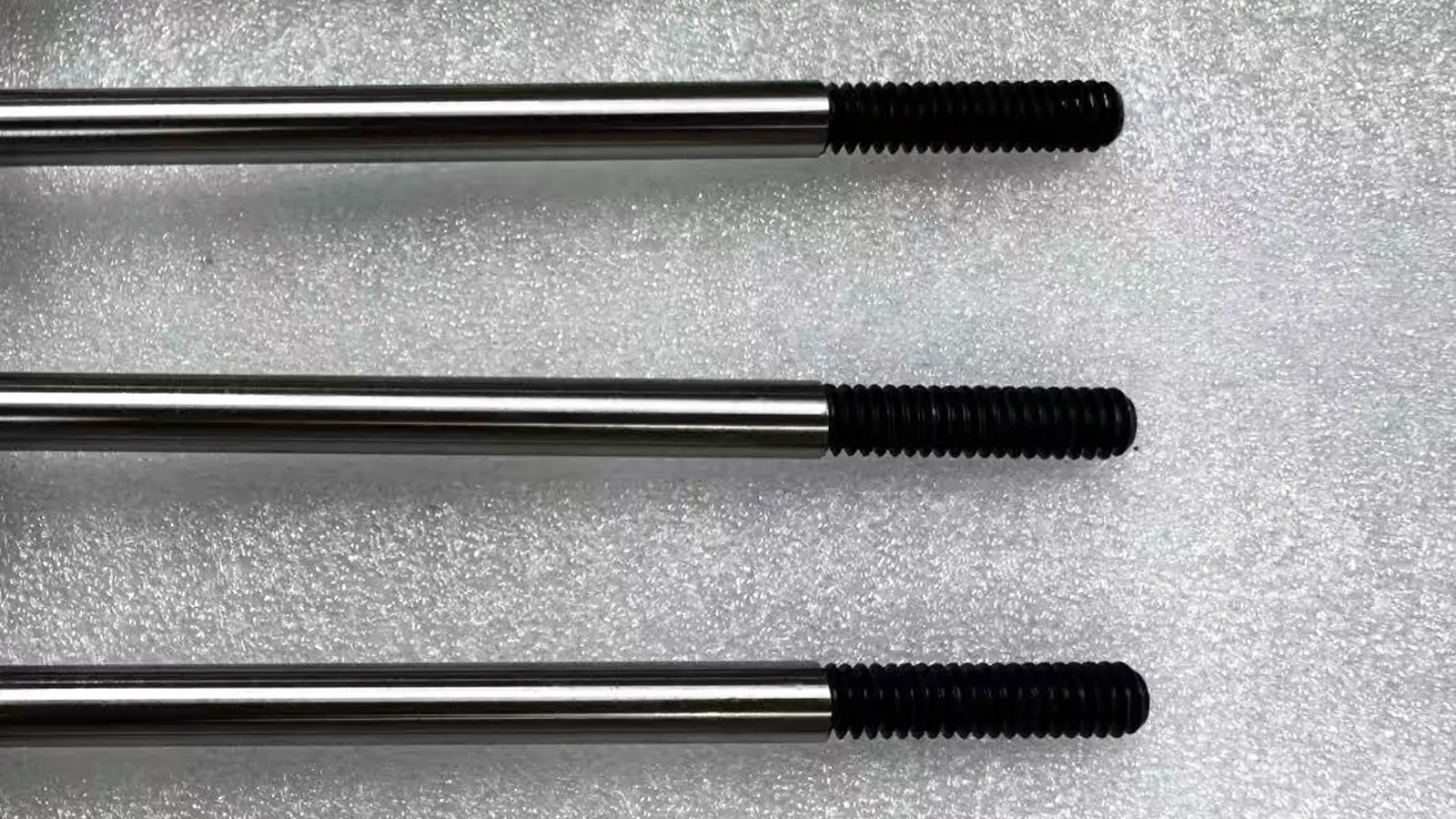
This design feature is cut with taps and external threads with dies. These can be used to cut threads to M2. It is a specific indication meaning that a thread’s normal diameter is 2.0 mm, the thread pitch is 0.4 mm, and tapping drip diameter is 1.6 mm as per ISO standard.
For anything larger than M2 specifically CNC threading tools must be used.
As for thread length, there is an interesting thing. The majority of the load is applied to the first several teeth (1.5 5 times the nominal diameter). It means that threads much longer than that are just unnecessary.
Another aspect is blind holes cut with taps (concerning everything smaller than M6).
Recommendation: M2 is minimal, but M6 or larger is optimal. The optimal thread length is 3 times larger than the nominal diameter of the tool.

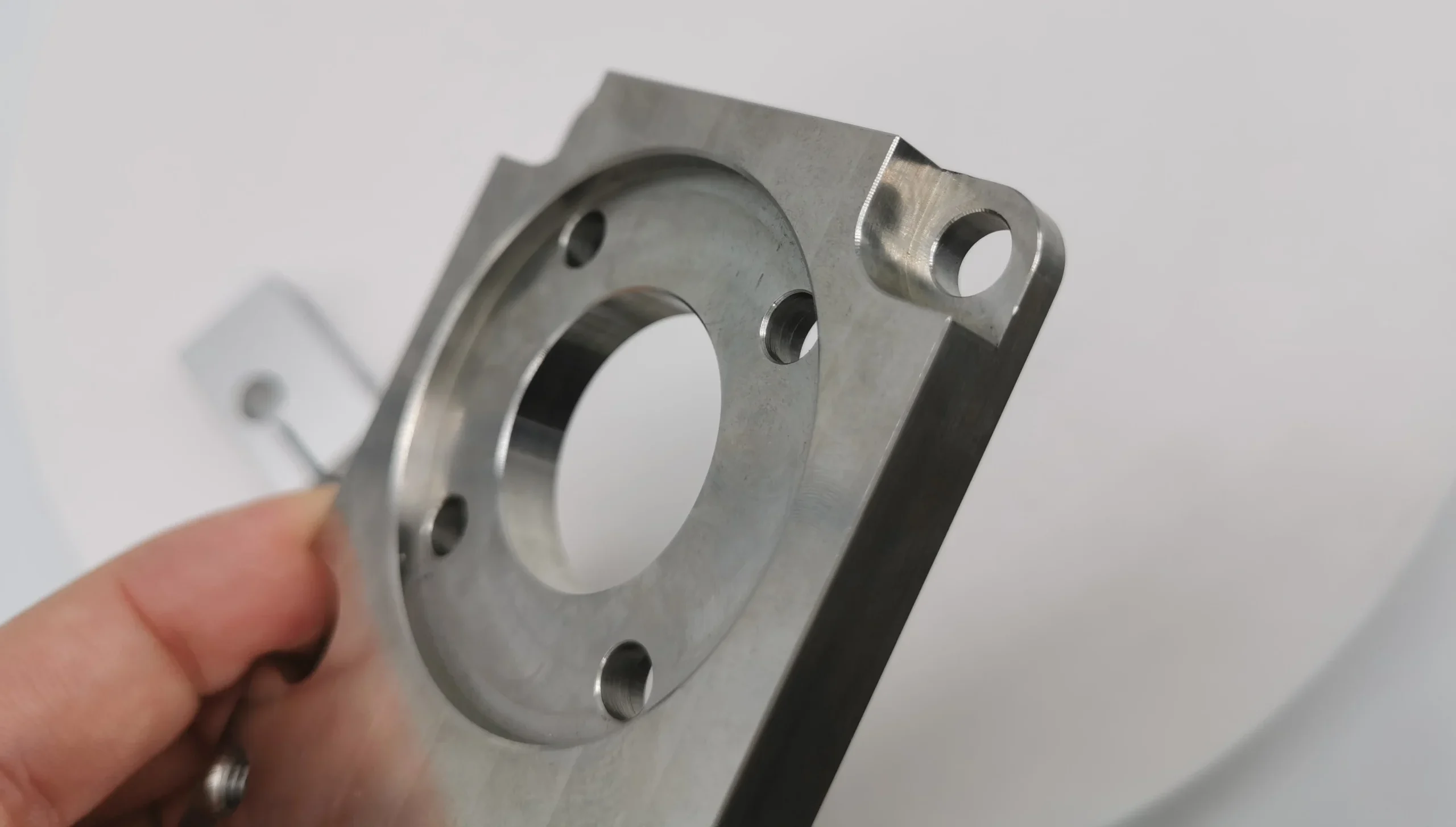
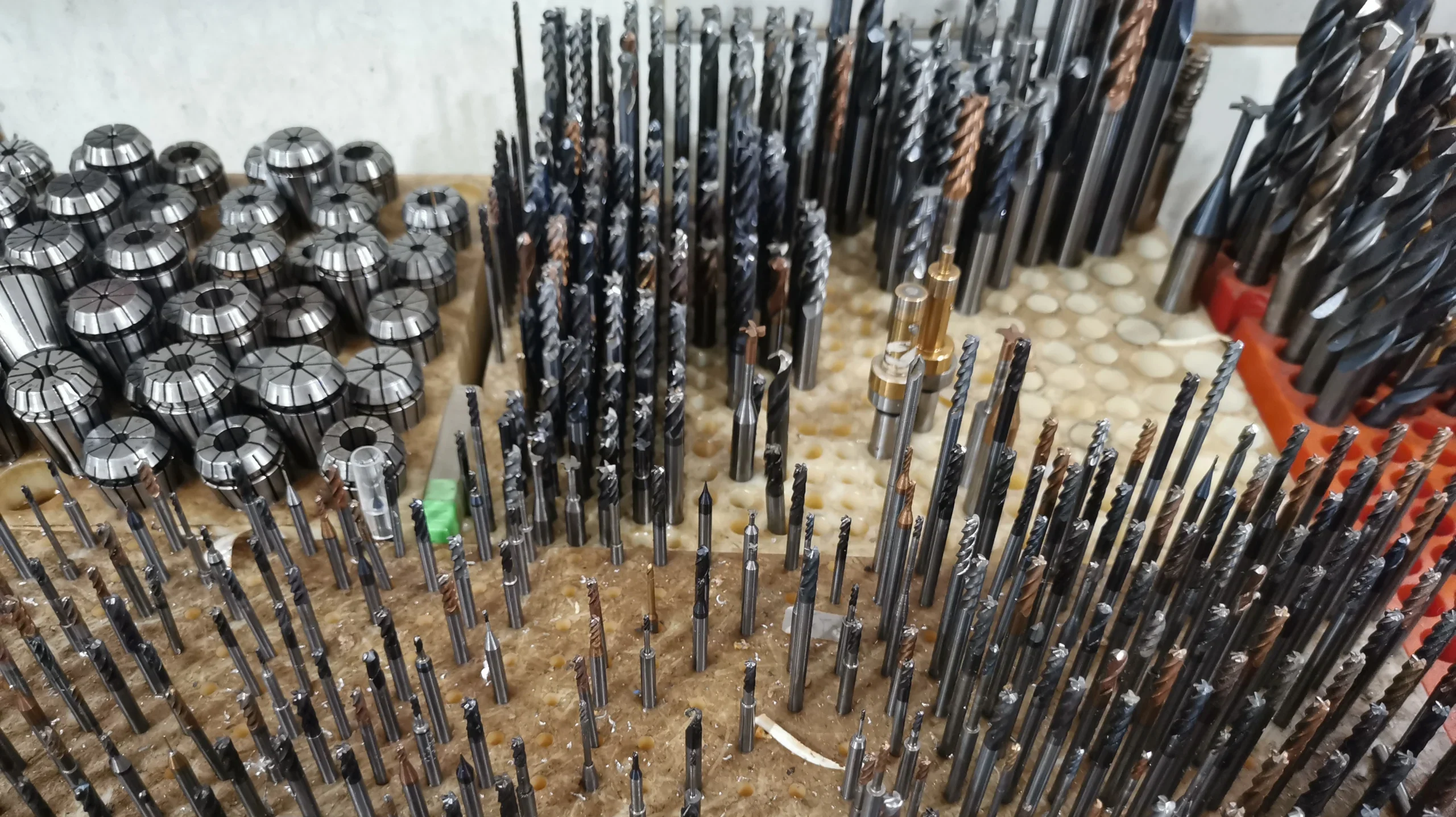
Here are the two vital considerations: diameter and maximum depth. CNC machines use drill bits and end mill tools. For holes with tight tolerances reamers and boring tools can be used. The sizes are typically standardized for the sake of design consistency.
As for non-standard holes, these must be machined with an end mill tool. For this purpose, it’s absolutely essential to stick to the maximum cavity depth restrictions. Holes deeper than normal ones are machined using advanced drill bits with a minimum diameter of 3 mm.
Blind holes must be machined with a drill bit having a conical floor of a 135-degree angle. Technically, there is no specific difference between though holes (normal ones) and blind holes.
Recommendation: any diameter larger than 1 mm (the length of a drill bit is set by default). The maximum depth to set while designing a model should be 4-10 times more than the nominal diameter.
Getting down to the engraving, here are some requirements to consider if you plan to place some form of text on your models. Engraving is preferred over embossing as it reduces the end waste of material.
You may use any standard font. This limitation is derived from the impossibility of engraving fancy fonts using conventional methods (the exception is laser engraving, but it’s another matter).
Recommendation: font size 20 or larger and Arial or Verdana as a font type.

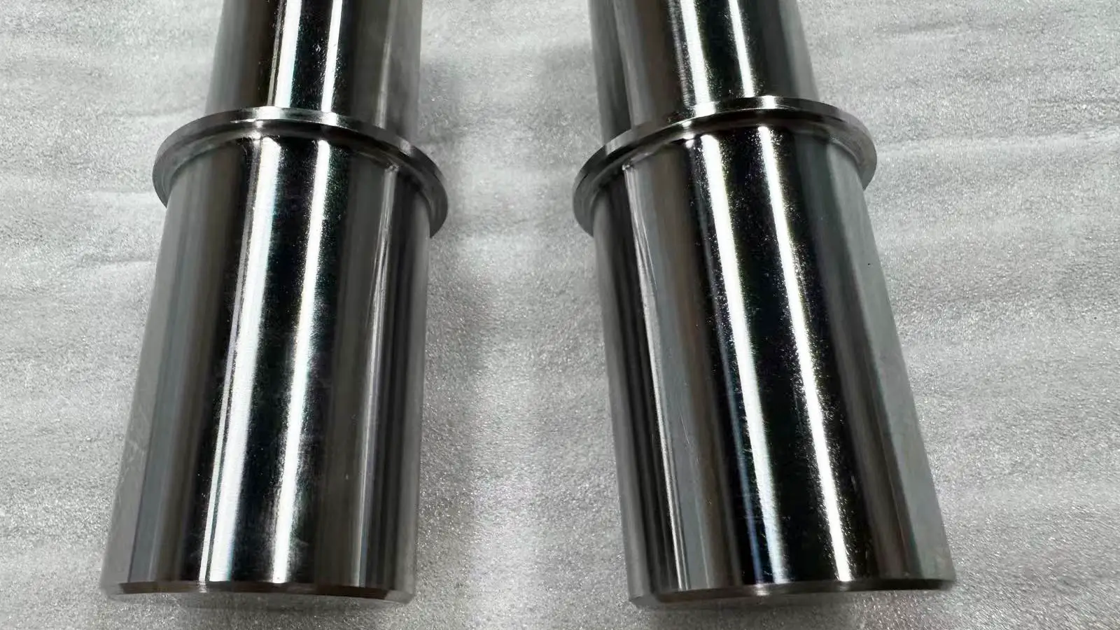
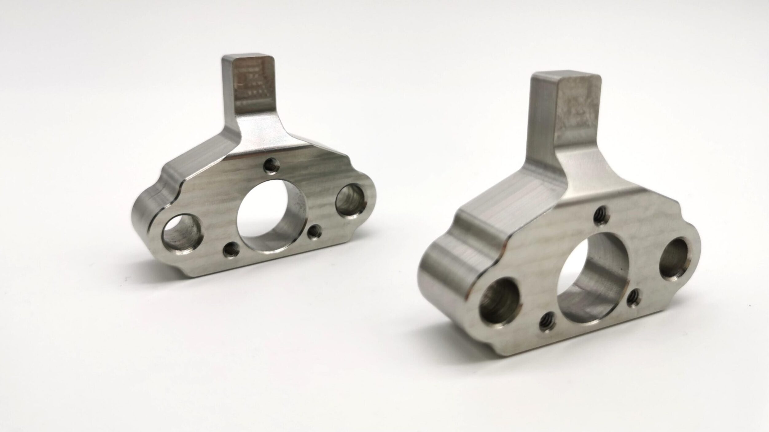
As well as with wall thicknesses and cavity depth there is some optimal value for internal corner radius. It implies the required usage of a suitable tool with an appropriate diameter that would comply with your design requirements.
As a vivid example of the impact of vertical corner radius adjustment is using the settings slightly above the recommended value. It allows following a circular path instead of a 90-degree angle. Or, it’s possible to use T-undercut to create a sharp 90-degree internal corner.
As for floor radius, end mill tools have a flat or slightly rounded finish, which you should consider while creating a design. Other floor radiuses can be machined with the help of ball end tools.
Recommendation: The vertical corner radius should be ⅓ times the cavity depth or larger. The floor radius should be 0.5-1 mm., or set no radius at all.
Related Post: How to Get Square inside Corners in CNC Machining
It’s hardly true that the same designs can be executed over workpieces from different materials. You had the example in the section about wall thickness where it was stated that plastic walls ought to be thicker than ones made of steel.
Some types of material do not suit the purposes of CNC machines overall. Others are difficult to machine. Stick to regular material types, as there are plenty of subtypes to meet any of your needs.
Recommendation: use industrial timber, steel, aluminum, and plastic as primary materials.
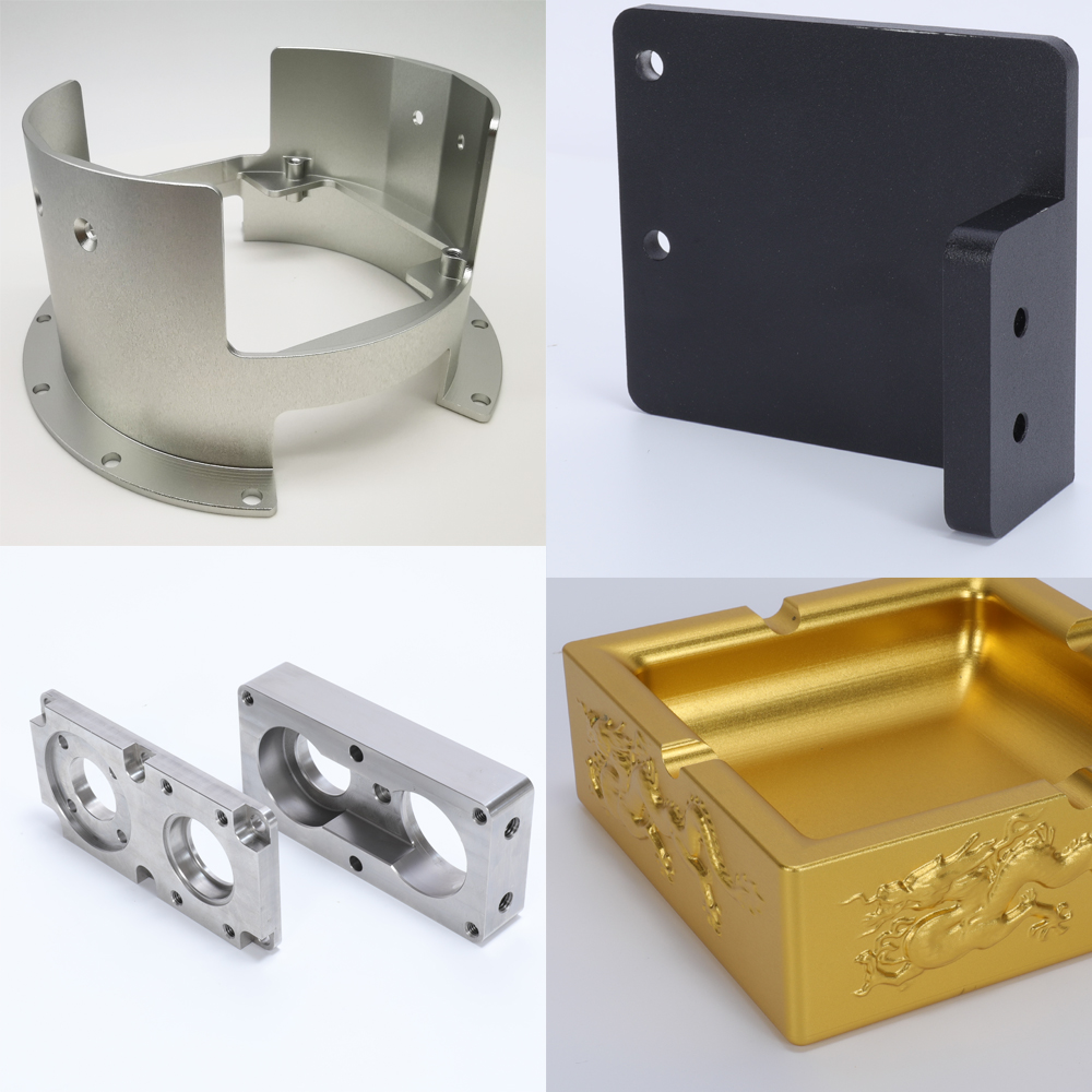
Surface finish is the last step in the matching process, it affects the appearance and surface hardness. For common materials, there has different types of options, such as anodizing, UV coating, electroplating, polishing, and so on.
When the surface finish is determined, you need to consider the thickness of the surface finish layer and design the proper part size.