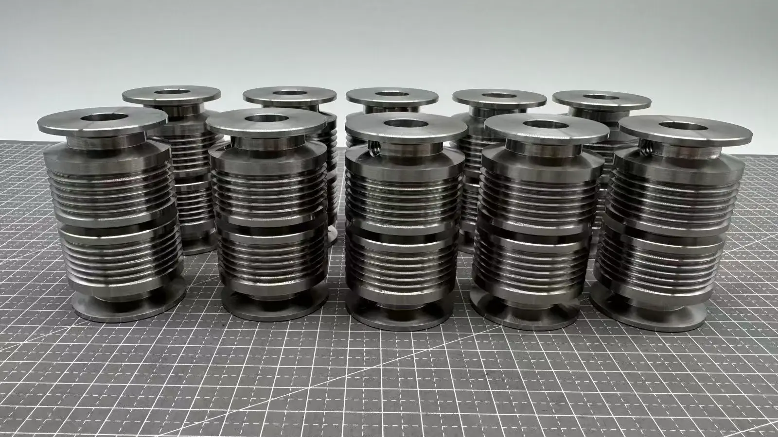
Circular runout GD&T plays a crucial role in ensuring the good quality and proper function of cylindrical parts. This part focuses on its definition and tolerance zone to detailed explain what is circular runout in GD&T.
Circular runout GD&T is a geometric tolerance used to control the variation of a part’s circular profile as it rotates 360° around the datum axis. By controlling the radial and axial runout of any cross-section, the GD&T circular runout controls the circular and concentrical deviation at the same time.
In short, circular runout GD&T confines how much the measured feature of a part swings referring to a datum feature(usually the cylindrical plane or the central axis).
And the controlled factors of circular runout include any out-of-roundness, eccentricity, and other deviations from a perfect circle, as well as the runout direction, as the feature rotates around its central axis.
As the circular runout GD&T controls both the radial runout and the axial runout, the tolerance zones are classified into two types.
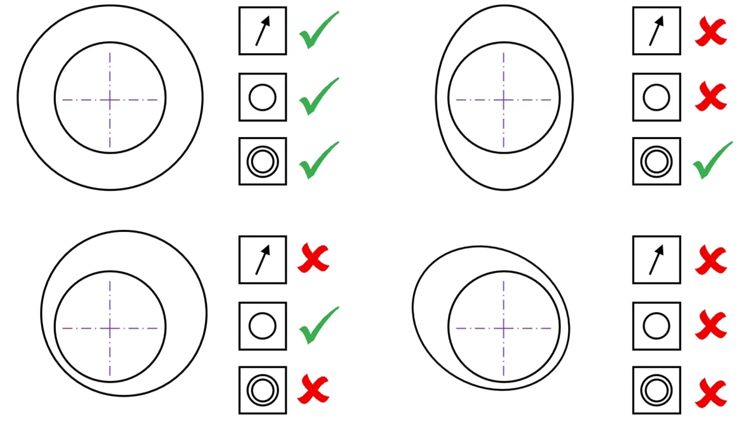
For radial runout, the tolerance zone is an area of a concentric ring. It controls that any cross-section that is perpendicular to the datum axis must lie within the zone between two concentric circles when rotating around the datum axis.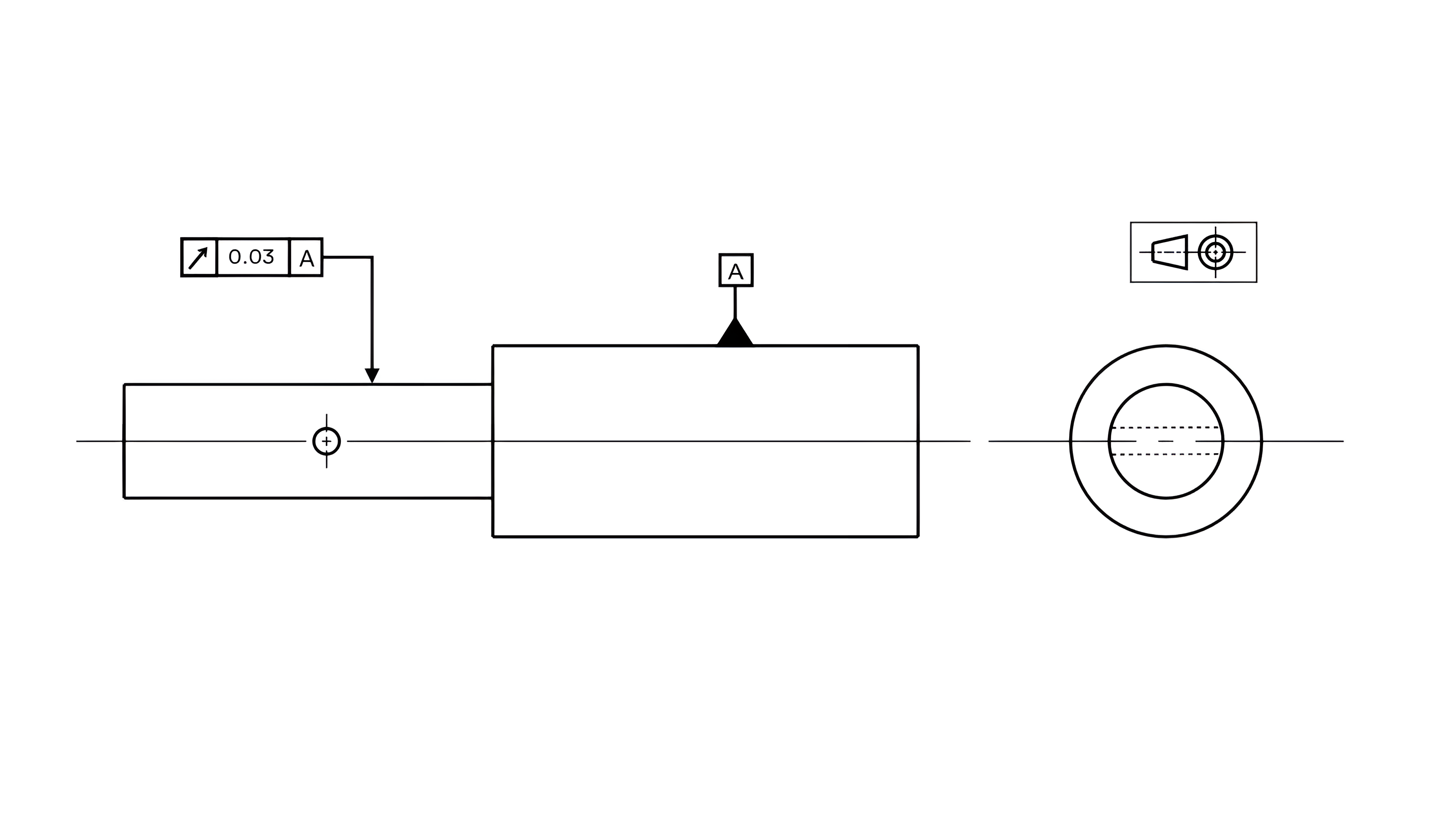
The center of these two concentric circles is the intersection of datum axis and the measured plane. And the tolerance value is the width of the concentric ring.
By confining the measured cross-section within this tolerance zone, the measured feature’s deviation on circularity, concentricity and axis’ straightness is controlled at the same time.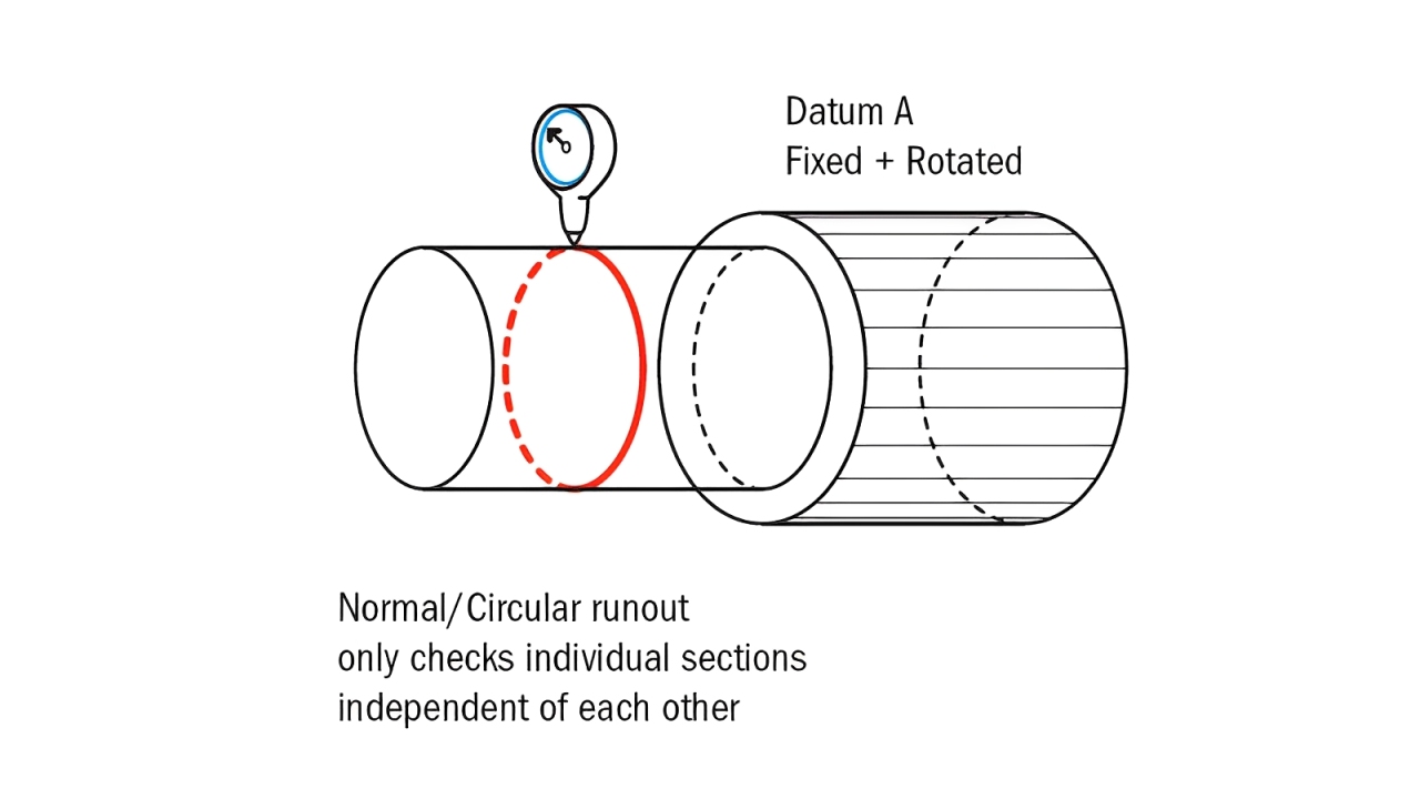
More importantly, note that the two concentric circles’ dimension is not essentially refined by the standard itself, but indirectly controlled by the size of feature and tolerance value.
As for axial runout, the tolerance zone consists of two parallel circles that are both theoretically perpendicular to the datum axis. The circumference line of the head surface or the end surface must lie within these two parallel circles when the measured feature rotating around the datum axis.
And the tolerance value is the width of these two parallel circles, which controls the permissible variation along the axial direction during rotation.
By controlling the measured feature within this tolerance zone, the measured surface’s flatness and perpendicularity to the datum axis are controlled at the same time.
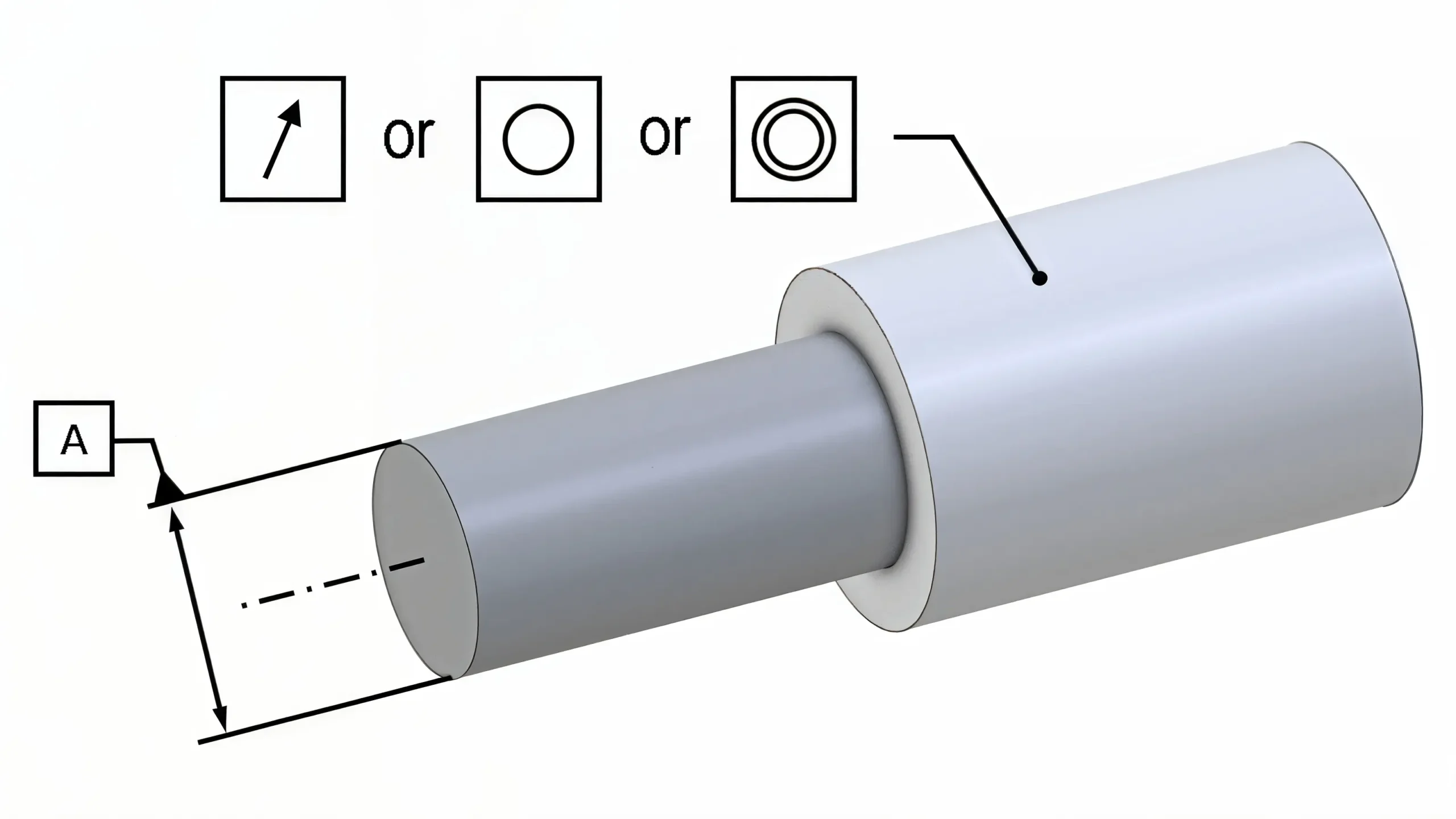
In addition, though the tolerance zone of circular runout would vary due to the different measured elements, one indication of circular runout tolerance can control both the radial and axial runout at the same time since the datum axis and tolerance value of radial tolerance zone are similar to that of axial tolerance zone.

Dial indicator is one of the most commonly used tools for circular runout measurement. This measuring method cost low and is suitable for on-site inspection. More importantly, the runout deviation is directly displayed.
However, the measuring accuracy of dial indicators is limited. And the measuring efficiency is certainly low, thus not suitable for high-volume rapid inspection.
The concrete steps to measure circular runout by this method are shown below:
Step 1: Fix the measured part on the precision rotating equipment(like a lathe, indexing head, or V-block), ensuring co-axiality with the rotational axis.
Step 2: Fix the dial indicator on a magnetic stand, with the probe perpendicular to the measured surface.
Step 3: Lightly press the probe to pre-compress the indicator by 1-2 turns, then rotate the dial to zero.
Steps 4: Slowly rotate the measured feature around the axis one full revolution, and record the difference between the maximum and minimum readings. Note to move the probe axially as needed to measure multiple cross-sections.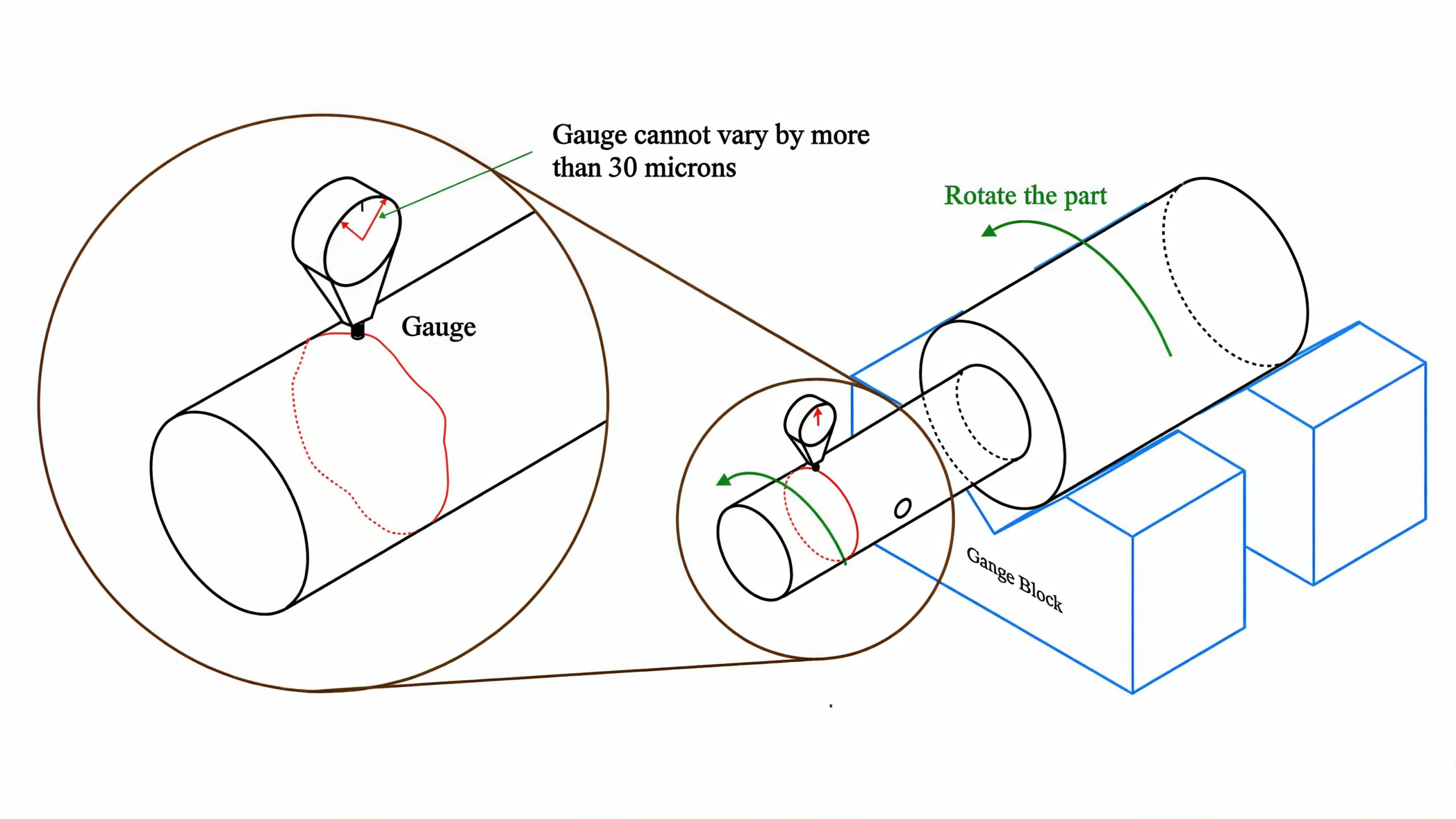
CMM is a kind of versatile machine that can be used to measure various GD&T tolerance, including circular runout GD&T.
The concrete steps to measure circular runout by this method are shown below:
Step 1: Establish a measurement coordinate system based on the datum axis of the part.
Step 2: Automatically collect data of multiple points along the measured circumference.
Step 3: Use the CMM software to fit the actual contour and calculate the maximum radial/axial deviation relative to the datum axis.
Step 4: Output runout values and visual graphs.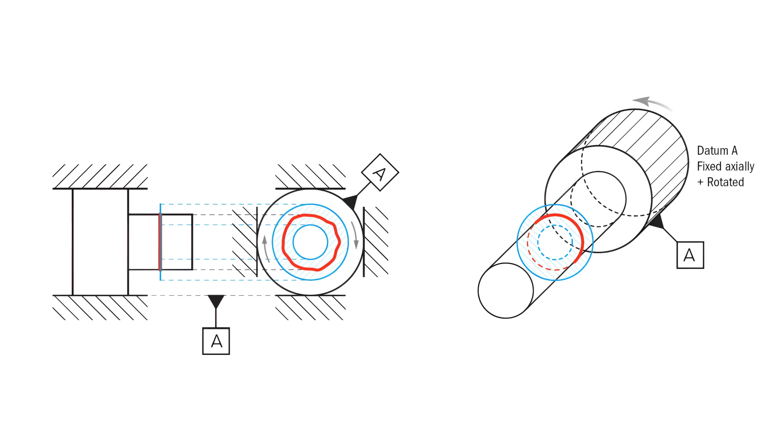
Roundness tester can also be used to measure circular runout. With high accuracy, it is designed specifically for runout and roundness. Thus, it is only suitable for rotary parts.
The concrete steps to measure circular runout by this method are shown below:
Step 1: Fix the measured part on precision spindle centers or V-blocks, adjusting the axis to be co-axial with the spindle.
Step 2: Set the radius and sampling density, and then use an inductive probe to contact the measured feature.
Step 3: Rotate the spindle and collect the data by the sensor, with the software analyzing the runout in real time.
Step 4: Output the maximum and minimum values of radial/axial runout.

MMC is a feature of size symbol which refers to the dimensional condition where the particular feature contains the maximum amount of material within its indicated tolerance.

LMC is a feature of size symbol which refers to the dimensional condition where the particular feature contains the least amount of material within its indicated tolerance.

Circular runout GD&T is a geometric tolerance used to control the variation of a part’s circular profile as it rotates 360° around the datum axis.

Total runout is one of the runout symbols that mainly controls the runout deviation of the measured feature’s entire surface during rotation around the datum axis.