In engineering, a fillet means intentionally smoothing out the sharp edges or corners of a part, creating a smooth, rounded transition between two intersecting surfaces.
Fillets are typically produced using CNC fillet tools and can be either convex (outside curves) or concave (inside curves).
Simply put, a fillet replaces a sharp interior or exterior corner with a smooth, continuous arc.
There are two common ways to classify fillets in engineering and mechanical design:
By Location (The CNC Shop View)
This is the most practical way to talk about fillets because it tells the programmer where the tool needs to go.
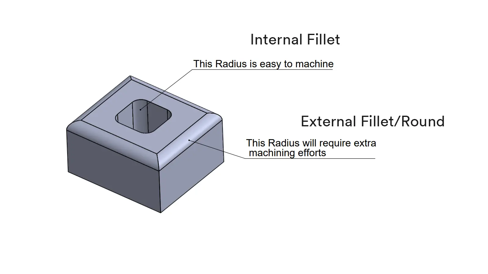
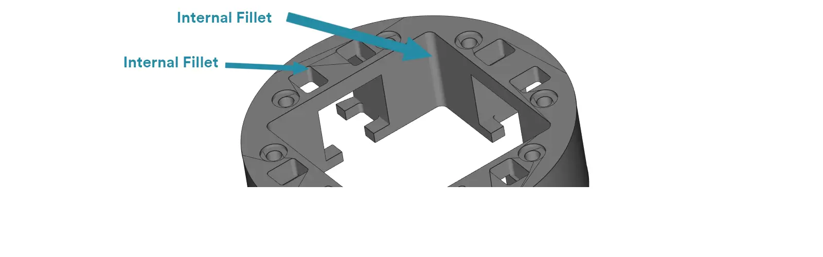
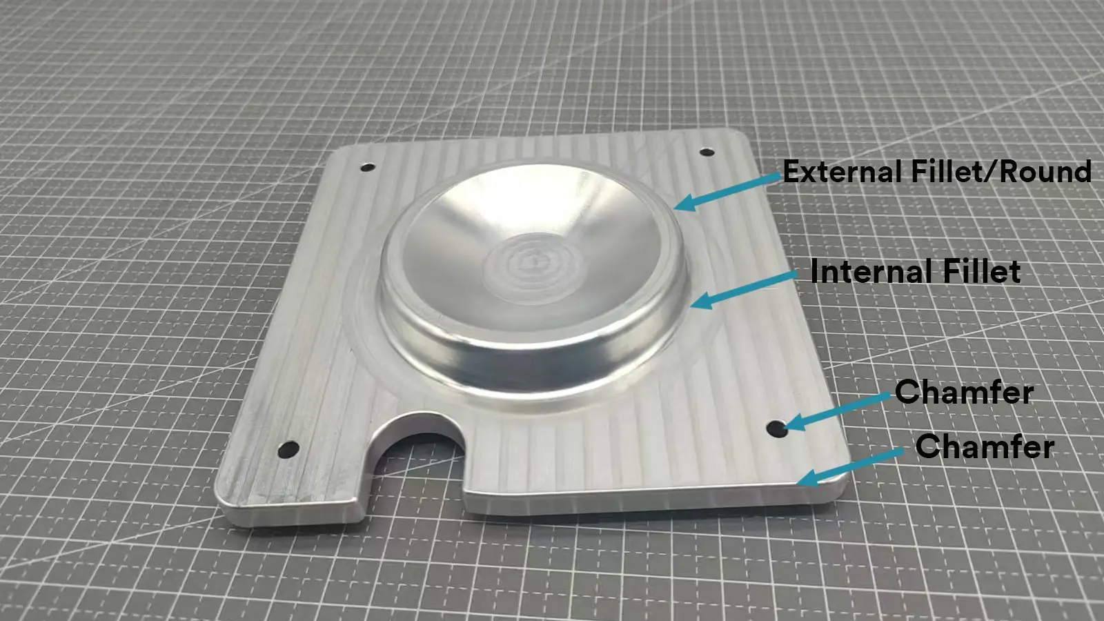
Internal Fillet: This is the curve you find on an inside corner—for example, the bottom of a pocket where two walls meet. What is a rounded corner called is internal fillet.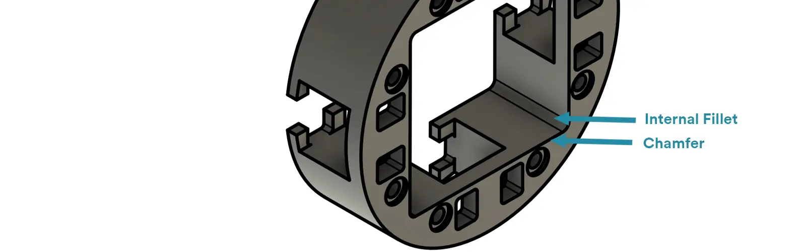
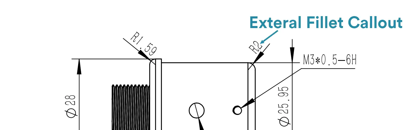
External Fillet: This is the curve on an outside edge or corner. When it’s on an exterior edge, we often just call it a Round.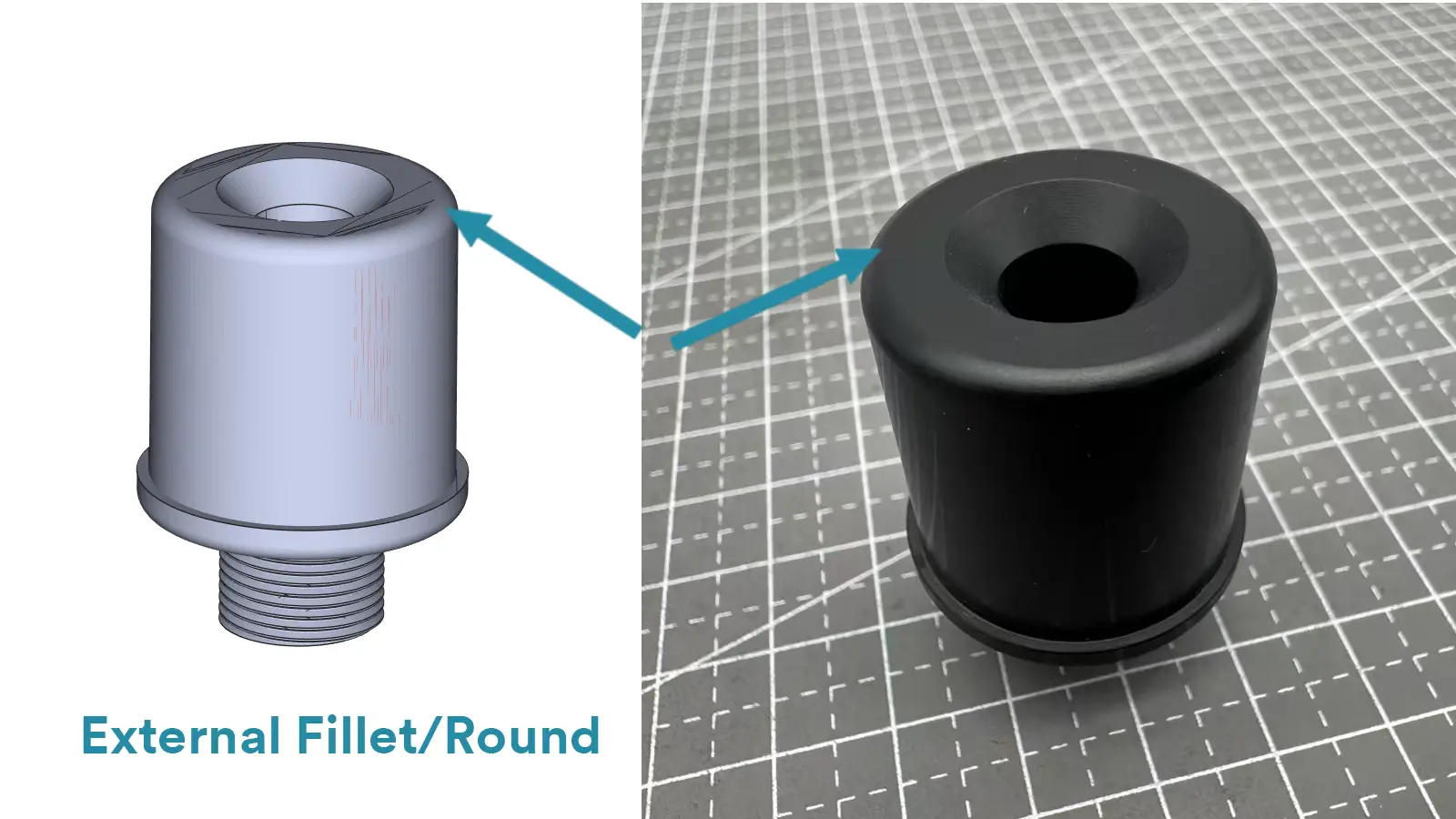
By Geometric Shape (The Designer’s View)
Concave Fillet: A curve that bows inward, like the interior of a bowl. (This is the same as an Internal Fillet.)
Convex Fillet: A curve that bulges outward, like a dome. (This is the same as an External Fillet/Round.)
An Internal Fillet is concave, and an External Fillet is convex. They are just two ways of describing the same fundamental geometry.
CNC Terminology Tips:
While all the terms above are correct, here’s what to keep in mind when talking CNC shop:
In modern engineering drawings and CNC manufacturing, fillets are primarily called out using the radius symbol (R), following key international standards such as ISO 129-1, ISO 8015, and ASME Y14.5.
ISO 8015 establishes fundamental rules for geometrical tolerancing, ensuring clarity and consistency.
ISO 129-1 defines the methods for dimensioning and tolerancing, including rules for radius callouts.
ASME Y14.5 is the core standard for dimensioning and tolerancing in the United States.
Following these standards ensures two things:
Clarity: There’s no room for guessing (no vague “sharp corner” notes!). The machinist knows the exact size needed.
Consistency: Every fillet on the drawing is communicated using the same, unified method.
Here are the most common ways you’ll see fillets documented on a drawing, moving from the most specific to the most general:
1.2.1. Direct Dimensioning
The most straightforward method: a dimension line points to the fillet, labeled with the radius symbol and value (e.g., R5 for a 5 mm radius).
Used for individual, critical, or varying fillet sizes.
1.2.2. Note-Based Callouts
Ideal when multiple fillets share the same size.
Local Note: A leader points to one fillet with a note like R3 TYP (where “TYP” means “typical,” indicating repeated features) or 4X R2 (meaning “four fillets, R2 each”).
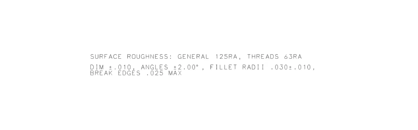
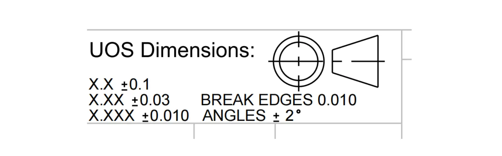
General Note: Placed in the drawing’s notes section, e.g., BREAK ALL SHARP EDGES TO R0.5.
1.2.3. Limit-Based Callouts
Used when a fillet must not fall below a minimum size (e.g., for tooling or strength).
Format: R0.5 MIN (the radius must be at least 0.5 units).
1.2.4. Model-Based Definition (MBD)
In advanced manufacturing today, the 3D CAD model is the true master blueprint. All the fillet sizes are already stored directly inside the 3D file.
The 2D drawing often serves only as a reference or a place to add critical notes.
Machinists use the 3D model to program the machine, making the digital feature itself the most accurate “callout.”
1.2.5. Implied by Linear Dimensions
If all corners of a part have the same fillet, the overall length and width dimensions may imply the fillet’s presence.
The manufacturer calculates the stock size based on these dimensions and the specified radius.
Key Considerations in Fillet Dimensioning
How to Design Internal Fillet Radii
Designing an Internal Fillet isn’t just a random choice; it’s a careful balance between structural strength, manufacturing cost, and tool availability.
Here’s a friendly, step-by-step approach to get it right.
Step 1: Define the Function & Load
Start by asking the basics: What is this fillet meant to do? Is its main job to reduce stress concentration, make assembly easier, improve fluid flow, or is it more for safety and looks? Also, understand how the part will be loaded—is it a constant static load, a repeating fatigue load, or a sudden impact?
For features like shaft shoulders or bosses: Try to make the ratio of the fillet radius (r) to the section height (d) as large as you can. A great rule of thumb to start with is r/d > 0.1.
For internal corners (like where a wall meets a base): A good practice is to make the fillet radius at least 20-30% of the local wall thickness.
Step 2: Set the Initial Radius
Now, let’s get practical and factor in how the part will be made.
General Wisdom: Brittle materials need more generous fillets. Remember, a very small radius does little to reduce stress.
In general, a larger radius means lower stress concentration and better fatigue life.
For CNC Machining (Your Go-To Rules):
Match Your Tool:
Your internal fillet radius must be at least as large as the cutter radius you plan to use (e.g., for a Ø4mm tool, your radius should be at least R2). To save time and money, always use standard tool sizes (like R0.5, R1, R1.5, R2, R3, R5). Designing a fillet that requires a custom tool is a recipe for added cost and delay.
Mind the Wall Thickness:
For critical areas, a good guideline is to make the fillet radius (R) at least one-third (⅓) of the thinnest wall thickness (t) it connects. So, R ≥ t/3.
Common Range:
For most CNC milled or turned parts, fillets between 1–6 mm are common (down to 0.5–1 mm for very small parts). Go larger for highly stressed areas.
For Sheet Metal Bending:
The inner bend radius is typically close to the material thickness (R ≥ t).
Step 3: Verify and Refine the Design
Once you have a starting radius, model it in your CAD software. This is the time to double-check for any assembly conflicts, part interference, or to ensure fluid flow paths are smooth.
Step 4: Validate with FEA (If Needed)
For parts under significant stress, run a Finite Element Analysis (FEA). This will show you the real stress levels and allow you to fine-tune the fillet radius to meet all strength and fatigue requirements.
Step 5: Finalize with Your Manufacturer
Have a chat with your machining partner! Confirm the standard tools they have available and agree on tolerances. Then, update your drawings clearly.
On your drawing, call out the fillet radius explicitly.
If the size is critical, specify a tolerance (e.g., R3 ±0.2) or a min/max range (e.g., R2 MIN / R4 MAX).
If there’s some flexibility, you can specify a range like R2–R4 or simply state “R2 MIN” to give the machinist some discretion.
How to Design External Fillet (Round)
External rounds are generally simpler.
Their main goals are safety and aesthetics, so the rules are far less restrictive. The R value here is just about the final shape.
Safety & Ergonomics: A small radius of R0.5 to R2.0 is often all you need to effectively break a sharp, dangerous edge.
Aesthetics & Feel: This is about product style. For instance, consumer electronics often use larger, palm-friendly radii for a premium feel.
Assembly: If the rounded edge needs to fit with another component, you’ll need to control its tolerance to ensure a proper fit.
| Type | Location (The Machinist’s View) | The Meaning of the R Value |
|---|---|---|
| Internal Fillet (Concave) | The inside corner between two planes. | CRITICAL: The R value sets the minimum size of the cutting tool radius used. |
| External Fillet/Round (Convex) | The outside corner between two surfaces. | SHAPE: The R value is simply a shape requirement; it doesn’t restrict the size of the cutting tool used. |
In CNC milling, the way we create an internal fillet is quite different from how we create an external one (often called a “round”). Understanding this difference is key to designing parts that are both functional and efficient to produce.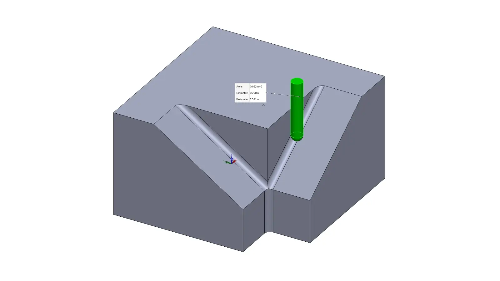
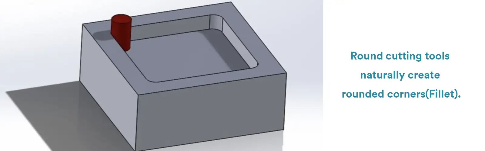
Think of an internal fillet as the natural result of the tool’s shape. This is the most common method in CNC milling.
The cutting edge of the tool itself has a specific radius, and by running this tool along the edges of your part, it directly creates the fillet.
Tool Selection is Key
The most important rule to remember is this: The radius of your internal fillet is fundamentally limited by the radius of the cutting tool. You must choose an end mill with a radius that is equal to or smaller than your desired fillet radius: Tool Radius ≤ Fillet Radius
A Helpful Tip: Go Big for Speed
To maximize material removal and shorten machining time, a CNC programmer typically chooses the largest diameter tool that can still create the required fillet.
For example, to make an R5 fillet, they would ideally use a 10mm diameter end mill (which has a 5mm radius).
How It’s Programmed
The programmer uses circular interpolation commands (like G02 or G03) in the G-code to guide the tool’s center point around the corner. This precise path leaves behind the perfect radius in the material.
The Fastest Way: Use a Specialized Tool
The quickest and most precise method is usually to use a ball nose end mill or a dedicated corner-rounding tool.
These tools have a pre-ground profile that matches your desired external radius exactly. They can create a perfect, consistent round in a single, efficient pass along the edge.
The Flexible Way: Use a Standard Tool
It’s also possible to create an external round using a standard end mill.
However, this requires the programmer to define an exact and often complex tool path, guiding the side of the tool along the edge to “sculpt” the rounded shape.
While flexible, this approach is generally slower and more programming-intensive than using a dedicated corner-rounding tool.
After a part is machined, we need to check if that R value (radius) and its tolerance meet the drawing specifications. The method we use depends entirely on the required precision and the location of the fillet.
Measuring External Fillets / Rounds (The Outside Edge)
Checking an internal fillet is tricky because the measurement tool often has limited access.
What they are: These are sets of precisely cut metal blades, where each blade has a known, calibrated radius.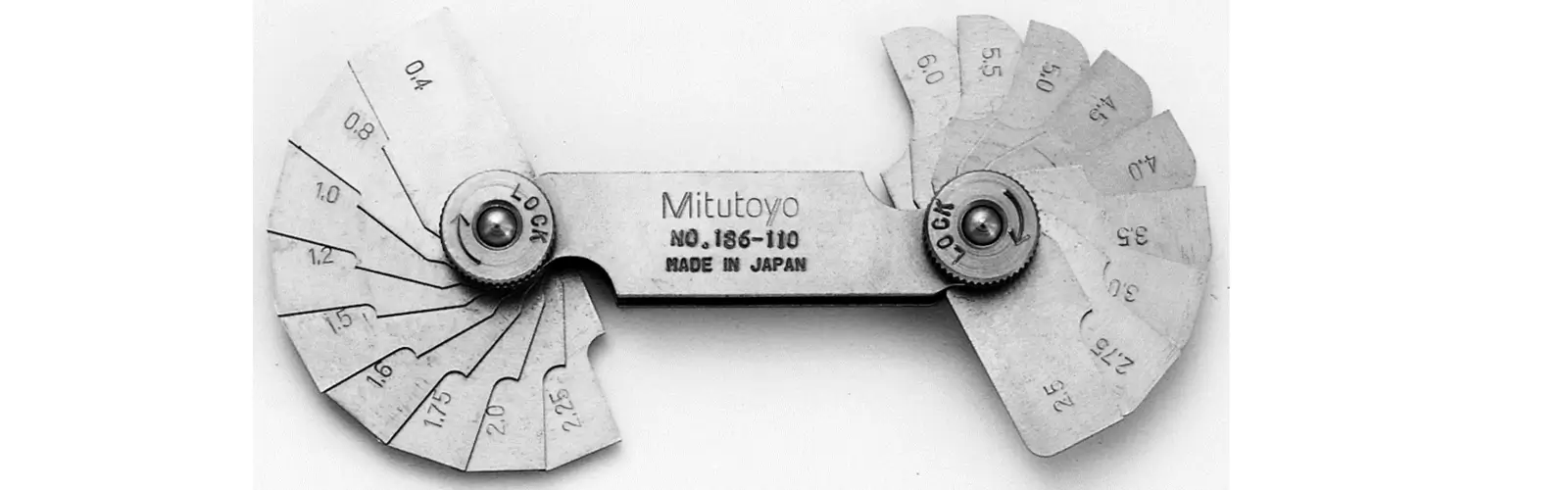
How it works: This is the quickest and simplest method. You simply place the metal blade against the machined fillet.
If there is little to no gap (no light shining through) between the blade and the part’s surface, the radius is a match!
The Catch: This is a Go/No-Go check. It confirms the nominal size, but it cannot give you a precise number for how far the actual radius deviates from the target.
What they are: A Coordinate Measuring Machine (CMM) uses a probe that physically touches the part, or a Vision System uses a camera to scan it. This is the gold standard for high-tolerance parts.
How it works: The probe or camera traces (or scans) multiple points along the arc. Specialized CMM software then uses complex math to calculate the Best-Fit R Value and determine exactly how much it deviates from your design.
Measuring External Fillets / Rounds (The Outside Edge)
External fillets are easier to check because they are fully exposed and accessible.
Just like with internal fillets, you use the calibrated metal blades to quickly check the external curve against the specified R value.
Some Vernier or Digital Calipers are equipped with curved jaws designed to sit flush against the fillet’s contact points. This allows the tool to provide a more direct and accurate measurement of the radius.
Optical Comparator: The part’s silhouette is projected onto a screen and compared against a magnified template of the design. This lets you visually check the entire profile of the fillet.
CMM: Again, this provides the most detailed, computerized analysis of the R value and the overall profile, perfect for critical parts.
Caliper: A standard caliper can sometimes be used to estimate the radius by measuring the change in the edge profile, but this is often considered a quick estimate, not a precision measurement.
Key Takeaways of Measuring Fillets:
For a quick, practical check, reach for your radius gages. When you need precise data for quality control, the CMM is your best friend. And for a handy direct measurement of external rounds, radius caliper jaws are a great tool to have.
Internal vs. External Fillets: Key Differences in Design, Manufacturing, and Inspection
| Feature / Attribute | Internal Fillet | External Fillet / Round |
|---|---|---|
| Primary Purpose | Reduce stress concentration, improve fatigue performance, facilitate assembly | Safety (remove sharp edges), aesthetics, ergonomics |
| Location | Inner corners, connecting two internal surfaces | Outer corners, protruding edges or features |
| Geometric Type | Concave arc | Convex arc (Round) |
| Design Constraints | R ≥ tool radius; R ≥ 1/3 of the minimum wall thickness; increase radius for fatigue-critical areas | R mainly for shape requirement; minimal restrictions from tooling; select based on aesthetics or safety |
| Typical Radius Range | Small CNC parts: 0.5–1 mm; general parts: 1–6 mm; larger for critical locations | R 0.5–2 mm for safety/sharp-edge removal; can be larger for appearance or assembly needs |
| Manufacturing Method | Use an endmill matching the radius; tool follows inner corner to cut the fillet | Use specialized corner rounding tools or radius endmills; can also use standard tools along the edge |
| Programming Considerations | Radius limited by tool size; tool radius must be ≤ desired fillet radius | No tool radius limitation; programmer defines path along the outer edge |
| Measurement Methods | Radius gauges (Go/No-Go), CMM, vision systems | Radius gauges, vernier calipers with radius jaws, optical comparators, CMM |
| Standard Drawing Callout | R + value (Internal Fillet) | R + value (External Fillet / Round) |
| Key Considerations | Too small inner radius can cause stress concentration and fatigue issues | Larger outer radius is safe; consider assembly fit and appearance |
While a fillet uses a curve to soften a corner, a chamfer uses a flat, angled cut. It’s the quick, cost-effective workhorse of CNC machining.
In engineering design, chamfering means the removal of a small, angled slice of material from an edge or corner to replace a sharp 90∘ angle.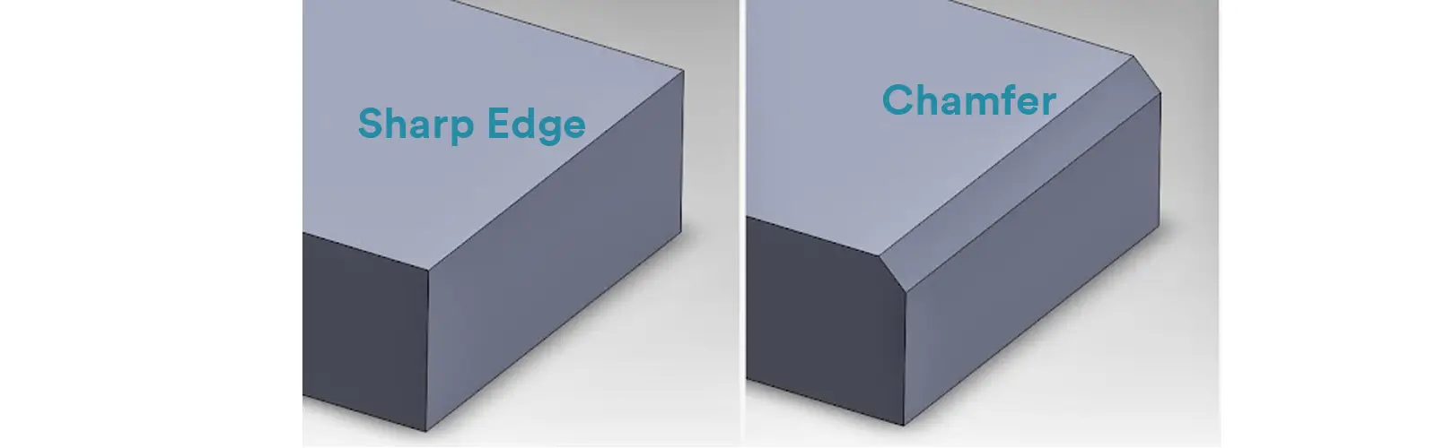
The Key Difference: Unlike a fillet (which is a curved, rounded surface), a chamfer is a flat, sloped surface—it looks like a simple, angled cut.
Chamfers are incredibly versatile. Here’s why they are so commonly used: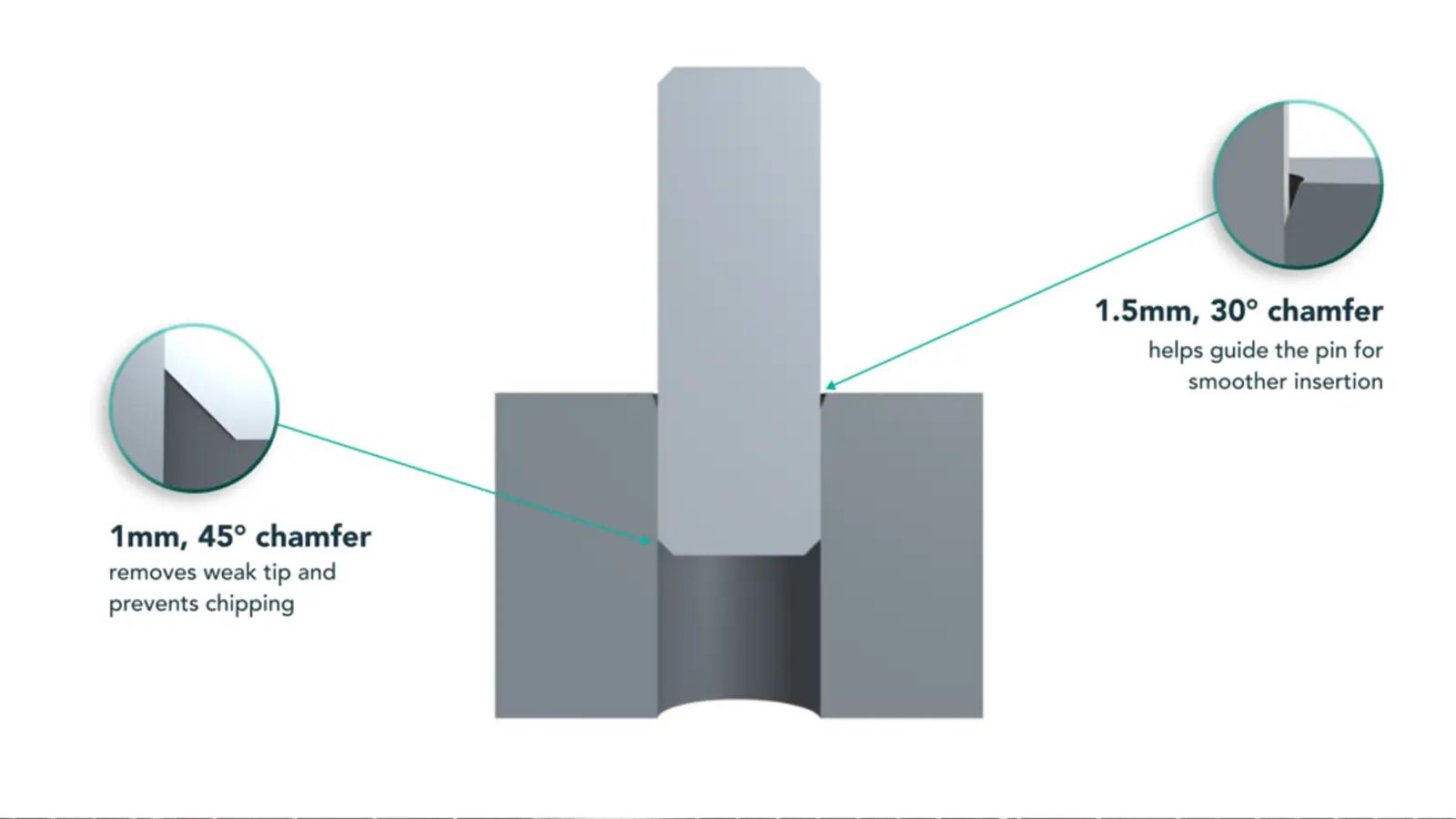
Easy Assembly (The Top Reason)
This is one of a chamfer’s most vital jobs. Adding a chamfer to the end of a shaft, pin, or screw creates a guiding surface. This acts like a funnel, helping parts slide smoothly into holes or bearings without getting stuck on misalignments or burrs.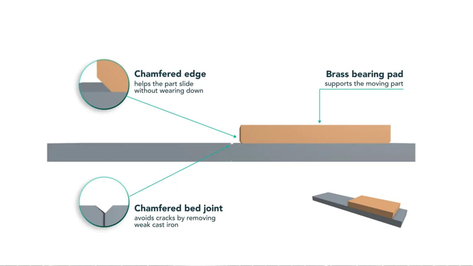
Safety First: Deburring & Breaking Sharp Edges
Just like a rounded edge, a chamfer removes dangerous sharp corners and machining burrs. This protects people handling the part from cuts and nicks. Often, a very small chamfer (like 0.2mm x 45°) is all you need to make a part safe to handle.
Managing Stress (In Specific Cases)
While not as effective as a fillet, a chamfer can still help reduce stress concentration. It removes the sharp corner and distributes stress over a wider area. It’s a great option when you need to relieve stress but a rounded profile isn’t suitable, like when a part needs to sit flush against a flat surface.
Creating a Machining Datum
At the start of a turning or milling job, a machinist will often cut a small chamfer on a raw material edge. This provides a clean, precise reference point for setting up tools and taking measurements.
Preparing for Welding & Fasteners
Chamfers are essential for strong joints. On a part that will be welded, the chamfer (often called a bevel or groove in this context) creates a channel for the weld material. This ensures the weld penetrates deeply, resulting in a much stronger connection than a simple surface weld.
Cost-Effective & Efficient
Chamfers are generally faster and cheaper to machine than fillets. A single, standard chamfering tool or end mill can create chamfers of many different sizes and angles. You don’t always need a special tool, which saves time and money.
Aesthetic Appeal
Beyond pure function, a chamfer can add visual interest. By breaking up a part’s silhouette with angled edges, it creates light-catching lines and shadows, giving the product a more refined and intentional look.
Chamfers can be categorized in a few helpful ways, depending on how we define them, where they’re located on a part, or what job they’re meant to do.
By Geometric Form
This is the most basic and crucial classification, as it determines the chamfer’s final shape and dimensional tolerance.
| Classification | Drawing Callout Format | Geometric Shape | Typical Applications |
|---|---|---|---|
| Equal Setback (45°) | C [Length] or [Length] × 45° | The chamfer surface is at a 45° angle to the original surfaces. The lengths of the two removed sides are equal. | Most common. Used for deburring, assembly guidance, and is the simplest and fastest chamfer to produce in CNC machining. |
| Two Distances (Unequal) | [Length L1] × [Length L2] | The distances L1 and L2 removed from the two original surfaces are not equal. | Used for specific fit adjustments, or to maintain uniform wall thickness on complex surfaces during multi-axis machining. |
| Distance × Angle | [Length L] × [Angle α] | Defines the length L removed from one original surface and the angle α between the chamfer surface and that same surface. | Welding preparations (Bevels), matching countersunk screws (e.g., 30° or 60°), and other special functional requirements. |
By Location on the Part
Where a chamfer is located determines the best tool and strategy to create it.
External Edge Chamfer: This is a chamfer on an outer corner or edge. It’s generally the easiest to machine, often done with a chamfer mill, an end mill, or even a countersink tool.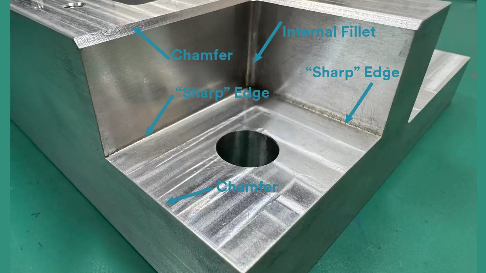
Internal Edge Chamfer: This is a chamfer on an inner corner or edge, like the entrance to a hole. It requires a tool that can fit into the space, and sometimes can be trickier to reach than an external chamfer.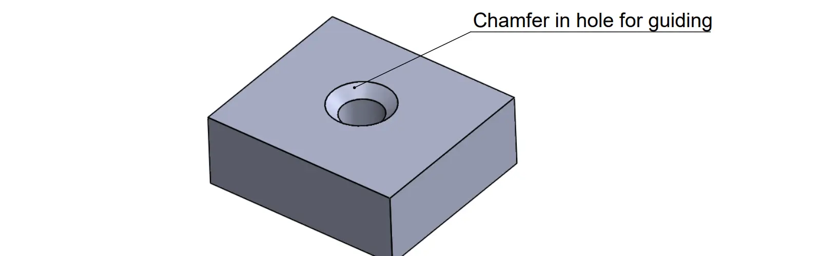
Hole Entrance Chamfer (AKA Countersink): This is a specific type of internal chamfer at the opening of a hole, typically designed to allow a screw head to sit flush with or below the surface.
By Functional Purpose
The reason why the chamfer is there usually dictates its size and how precisely it needs to be made.
| Classification Name | Function / Purpose | Typical Size | Precision Requirement |
|---|---|---|---|
| Deburr / Safety Chamfer | Eliminates sharp edges left after machining to protect operators and make parts safe to handle. | C0.2 to C0.5 (or R0.2 MAX) | Very Low. Only needs to remove the sharp corner. These are usually noted in the general blueprint instructions. |
| Assembly Lead-in Chamfer | Acts as an angled ramp or guide surface, helping components (like shafts or pins) smoothly enter holes or slots. | C0.5 to C2.0 | Medium. The size is large enough to guide the part, but the tolerance is moderate. |
| Fastener Fit Chamfer | Used for installing screw heads or rivets, ensuring the head sits perfectly flush and level with the surface of the part. | Angle is usually 82° (for American screws) or 90° | High. Angle and depth tolerances must be strictly controlled to achieve a perfect, flush fit. |
| Weld Bevel Chamfer | Creates space for the welding material (filler metal) to penetrate deep into the joint, ensuring the weld achieves the required structural strength. | Angle and length (e.g., 30° bevel, 2mm depth) must be strictly controlled | High. Directly impacts the structural integrity and strength of the welded joint. |
By Geometric Form
Equal-Leg Chamfer: Both sides of the chamfer are the same length. This is the standard and most common type.
Unequal-Leg Chamfer: The two sides of the chamfer have different lengths. This is used for specific assembly or strength requirements where a symmetric chamfer isn’t ideal.
Single-Sided Chamfer: Only one edge of a corner is chamfered.
Multiple Chamfers: When the same chamfer is applied to several edges. This is often noted on drawings with a quantity, like 4X 1×45°, meaning “apply this 1×45° chamfer to four edges.”
Standards
The method for dimensioning and calling out chamfers is standardized internationally. The primary standards to follow are:
ISO 13715: Specifies technical drawing standards for edges and their conditions.
ISO 129-1: Covers the general principles of dimensioning and tolerancing on technical drawings.
ASME Y14.5: The definitive standard for Geometric Dimensioning and Tolerancing (GD&T) in the US, which includes rules for defining features like chamfers.
ASME Y14.6: Provides detailed specifications for screws, threads, and chamfers.
Common Callout Methods with Examples
Below are the standard ways to specify a chamfer on an engineering drawing, with practical examples.
| Callout Method | Description & Application | Example & Illustration |
|---|---|---|
| Size × Angle | This is the preferred and recommended method per ASME Y14.5 and ISO standards. It is the clearest, as the machinist can directly understand the required dimensions. It’s shown in a view where the chamfer and both original surfaces are visible. | 1 × 45° Indicates a chamfer with a 1 mm length at a 45° angle. |
| “C” Notation (Default 45°) | A convenient shorthand. When only a length is given with the letter ‘C’, it is universally understood to mean a 45° chamfer. This is the most common callout for general deburring and assembly guides due to its simplicity. | C1 This is exactly equivalent to 1 × 45°. |
| Multiple Chamfers | Used to efficiently call out the same chamfer on multiple edges. The quantity is specified to avoid repeating the same note. | 4X C1 or 4X 1 × 45° Means “apply this 1 × 45° chamfer to four edges.” |
| Unequal Leg Chamfer | Used when the chamfer removes different amounts from the two original surfaces. This is necessary for special fits or geometric adjustments. Two orthogonal views are typically required to clearly show both distances and avoid ambiguity. | 2 × 3 Indicates an unequal chamfer with leg lengths of 2 mm and 3 mm. |
| Hole Entrance Chamfer | Specifies a chamfer at the entrance of a hole, often for a fastener. The callout is typically placed with the hole diameter. | Ø10 +0.2/-0 × 1×45° A 10 mm diameter hole with a 1 × 45° chamfer at its entrance. |
| Linear Chamfer | For a chamfer that runs along a long edge, a combination of a linear dimension and a leader note is used. The dimension locates the start and end, and the leader specifies the chamfer geometry. | [Illustration: A long edge with a dimension line along it and a leader pointing to the chamfered face with the note 2 × 45°] |
An example of Size × Angle chamfer callout 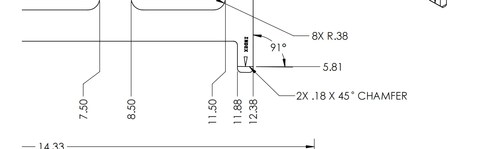
An example of Limit chamfer callout
General Chamfer Note
The Best Practice for Chamfer Callout
For drawings with many identical chamfers, using a general note keeps the drawing clean and is considered a best practice.
Specifying a Default:
ALL CHAMFERS 1.5 × 45° UNLESS OTHERWISE SPECIFIED
Specifying Unnoted Chamfers:
ALL UNSPECIFIED CHAMFERS 1 × 45°
BREAK ALL SHARP EDGES 0.5 × 45°
When designing a chamfer, you must follow a clear priority list. This order ensures your part works correctly and is manufactured efficiently:
Function (Fit/Lead-in)≫Manufacturing Cost (45∘ Simplification)≫Edge Safety
Step 1: Start by asking the most important question: “What is the main job of this chamfer?”
The answer will determine the required size, angle, location, and tolerance.
Chamfer Design Function Guide table
| Design Objective | Application Scenarios | Design Points & Recommended Sizes |
|---|---|---|
| Ease Assembly (Most Common Function) | Shaft ends, pin holes, threaded holes, guiding features. | • The chamfer size must be large enough to provide an effective lead-in. • Rule of Thumb: The chamfer should be slightly larger than the expected misalignment. • Recommended Range: For standard shafts/holes, C0.5 to C2.0. |
| Reduce Stress Concentration | When a fillet is not desired, but stress relief from a sharp corner is needed. | • Less effective than a fillet, but far better than a sharp corner. • The stress concentration factor decreases as the chamfer size increases. • For critical areas: Finite Element Analysis (FEA) may be required for size optimization. |
| Deburring & Safety | All machined edges, especially on parts handled by personnel. | • A very small chamfer is sufficient, often just to break the edge. • Recommended Range: C0.1 mm to C0.5 mm (or specified as a maximum, e.g., 0.5 MAX). |
| Meet Process Requirements | Tool run-out grooves, weld preparations, edges of sealing grooves. | • The size is dictated by the specific process. • Example: A thread relief groove’s width and depth must adhere to thread standards. |
Is it an Assembly Lead-in? (Needs a moderate C1.0 to C2.0 size.)
Is it a Fastener Fit? (Needs a precise angle like 82∘ or 90∘.)
Is it just for Deburring/Safety? (Needs a tiny C0.2 or C0.5 MAX.)
Step 2: Perform DFM (Design for Manufacturing) Analysis
Once you know the purpose, check if the required chamfer is practical and cost-effective for the CNC shop.
Standard Tooling: If the design is feasible, verify that a standard tool (like a 45∘ chamfer mill) can achieve the required cut.
Non-Standard Needs: If your design requires an unusual angle (like 37∘) or a complex profile, you must consider whether the cost of a custom non-standard tool or a slower, multi-axis tool path is worth the functional benefit. If not, try to modify the chamfer data to fit standard tools.
Step 3: Clearly Document the Callout
After the function and feasibility are confirmed, use the most appropriate geometric format to document the chamfer on the blueprint.
Design Summary:
| Feature Type | Priority | Best CNC Practice |
|---|---|---|
| Functional Chamfer | Function > Cost | Precisely call out using [Length] × [Angle] or C[Length] with tight tolerances. |
| Non-Functional Chamfer | Cost > Function | Standardize 45° chamfers whenever possible, or use general notes like C0.2 MAX for bulk deburring. |
In CNC milling, creating a chamfer is often one of the fastest and most economical tasks. It typically requires only a specialized Chamfer Mill or a standard end mill. Chamfers can also be made via turning and grinding
The best method depends entirely on the machine you are using and the angle you need.
Chamfers Production Methods
| Method | Best For | Key Takeaway / Details |
|---|---|---|
| Chamfer Mill (Dedicated Tool) | Production work on CNC mills, especially for standard 45° chamfers. | Fastest and most efficient. This specialized, angled tool makes a quick, clean cut in a single pass, minimizing cycle time. |
| Standard End Mill (Square) | Flexibility when a dedicated chamfer mill isn’t available. | A good backup, but slower and less precise on angles. This method requires more complex programming to calculate the diagonal tool path. |
| Turning (Lathe) | Any cylindrical/rotational part (shafts, rods). | The simplest and most natural method. On a lathe, the turning tool is simply angled and fed across the edge to quickly and naturally create the chamfer. |
| Special Angle Tools (30°, 60°) | Weld bevels or highly precise non-45° fastener fits. | Requires a specialized angled tool or complex 3- or 5-axis programming to tilt a standard tool into the correct position. |
| Drilling | Creating a small lead-in on the rim of a hole. | The drill bit’s point angle (usually 118° or 90°) naturally creates a small, functional chamfer as it enters the material. |
| Filing / Grinding | Prototyping, repairs, or one-off parts. | Manual skill. Use this only when no machine is available; it is slow, inconsistent, and completely dependent on the operator’s skill. |
Verifying a chamfer is crucial to ensure its dimensions—the length and the angle—match the blueprint. The measurement method you use depends on the chamfer’s complexity and the required precision.
Measuring a 45° Chamfer
A 45° chamfer (often called out as C [Length]) is the simplest to measure, as you typically only need to verify the length of the removed edge.
Tool: Digital Caliper or Depth Gage
How it works: Place the caliper’s main jaw flat on one of the original part surfaces. Then, use the depth-measuring blade (or the tip of the caliper jaws) to measure the distance to the start of the chamfered surface.
Why it’s great: It’s fast and direct. Because a 45° chamfer has two equal sides, confirming one length is all you need to verify the size.
Measuring a Non-45° Chamfer (Angle × Length)
For these chamfers, you need to verify both the angle and the length.
Tool: Universal Bevel Protractor or Dedicated Chamfer Gage
How it works: A bevel protractor has an adjustable blade that you set against the chamfer surface to get a precise angle reading. A chamfer gage is a simpler, go/no-go tool with fixed angles (like 30°, 45°, 60°) for quick comparative checks against standard sizes.
The Gold Standard for All Chamfers
Tool: CMM or Vision Measurement System
How it works: This is the most accurate method. A CMM probe touches multiple points along the chamfer surface. The software then fits these points to a plane and a line, calculating the exact angle and length with high precision and checking them against the specified tolerances.
Best for: Critical features, quality control documentation, and whenever you need the highest level of confidence.
Chamfer Measurement Methods Comparison Table
| Method | Description | Tools | Advantages | Disadvantages |
|---|---|---|---|---|
| Visual & Tactile Comparison | The most basic method. For deburring/safety chamfers only, assessed by sight and touch. | Naked eye, by hand | • Instant feedback • Zero cost | • No quantitative data • Entirely subjective |
| Calipers / Depth Gauge | The most common, direct method for quantitative measurement. | Vernier Calipers, Depth Gauge | • Widely available tools • Simple to operate • Accuracy sufficient for most industrial applications | • Difficult for very small chamfers • Cannot measure angle directly |
| Optical Comparator | A high-precision, non-contact measurement method. | Optical Comparator | • Non-contact • Fast • Can measure both size and angle simultaneously • Ideal for small, precision parts | • Requires expensive equipment • Typically for 2D measurement only |
| CMM | The highest-precision, authoritative measurement method. | Coordinate Measuring Machine (CMM) | • Very high accuracy • Can generate authoritative inspection reports • Can measure chamfers in complex locations | • Very expensive equipment • Complex operation required • Slow measurement speed |
| Specialized Gages / Templates | Method for rapid inspection in high-volume production. | Go/No-Go gages, Angle templates | • Very fast verification • No specialized skill needed | • Only provides qualitative (pass/fail) judgment • Cannot provide specific numerical values • Requires custom fabrication |
We’ve covered a lot about fillets and chamfers—what they are, their types, uses, how they’re made, and how to measure them. While both are used to soften sharp edges on a part, they differ in shape, function, and cost.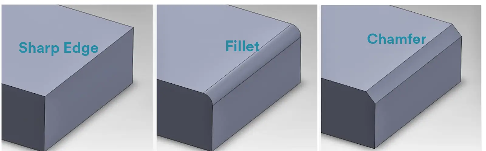
In engineering and CNC machining, when we compare Fillets and Chamfers, we’re usually focusing on external edges. That is, an External Fillet (or Round) versus an External Chamfer.
Why the Internal Corner Comparison is Rare
For internal corners (pockets, cavities):
Internal Fillets are nearly mandatory. They are the best way to reduce stress concentration, prevent cracks, and boost a part’s fatigue life.
Internal Chamfers are rarely used for design purposes. They usually only appear when required by a specific manufacturing process (like a tool exit groove) or a rare assembly need, and are not a substitute for a fillet.
| Feature | External Fillet (Round) | External Chamfer |
|---|---|---|
| Definition | A smooth, convex curved edge connecting two external surfaces, replacing a sharp corner with a radius. | A flat, angled cut on an external edge, removing a portion of the corner to form a sloped surface. |
| Primary Purpose | Safety, aesthetics, stress reduction, smooth transitions for mating parts. | Safety, assembly guidance, edge preparation for welding or fasteners, aesthetics. |
| Geometric Shape | Curved/rounded transition; continuous radius. | Flat/sloped transition; straight planar surface. |
| Common Angles / Radius | Radius R varies based on design, standard tooling, or functional requirements; no strict angle. | Angle commonly 45°, length C defined; other angles possible (30°, 60°) for specific functions. |
| CNC Manufacturing | Machined with round-over or ball-end mills; radius must ≥ cutter radius; may require multiple passes for large radii. | Machined with chamfer mills or standard end mills; single-pass machining possible; faster and cheaper for standard angles. |
| Tooling Limitation | Tool radius limits minimum fillet radius; larger radius requires larger tool or multiple passes. | Standard chamfer tools or end mills suffice; angle must match tool or program tool path precisely for non-standard angles. |
| Stress & Strength Impact | Reduces stress concentration; improves fatigue life in edges exposed to load. | Slightly reduces local stress; less effective than fillets in fatigue-critical areas. |
| Drawing Callout / Standards | Radius R; ISO 129-1, ISO 8015, ASME Y14.5; can specify R min/max if critical. | Length × angle (C × θ); ISO 13715, ISO 129-1, ASME Y14.5/14.6; default 45° if not specified. |
| Measurement Methods | Radius gauges, CMM, or vision system for high-precision verification. | Digital calipers for 45°, bevel protractors/chamfer gauges for non-45°, CMM for high accuracy. |
| Cost & Efficiency | Tooling may be specialized; machining multiple radii can increase time and cost. | Typically lower cost; standard chamfer tools can produce in a single pass; efficient for batch production. |
| Aesthetic & Safety | Smooth, rounded look; eliminates sharp corners, visually appealing. | Breaks sharp edges; provides safety and functional guide surfaces; visually precise lines. |
| Design Considerations | Radius chosen based on ergonomics, stress distribution, assembly, and aesthetics; usually larger radius for fatigue-critical edges. | Angle and length chosen based on assembly fit, tooling limits, or edge removal requirements; typically standardized 45° for simplicity. |
Choosing between a fillet and a chamfer depends on your part’s main objectives: structural strength, assembly functionality, or manufacturing cost. It’s a process of trade-offs and compromises.
The most important concept to remember is that Internal Fillets are almost always mandatory for strength, while the choice between a Round (External Fillet) and a Chamfer is primarily about cost and function.
Here’s a clear decision-making guide:
| Priority Goal | Recommended Feature | Ideal Application | Reasoning |
|---|---|---|---|
| Structural Strength & Durability | Fillet | Internal corners; transition areas between loaded sections | The arc effectively distributes stress, significantly improving fatigue life under cyclic loading. The preferred choice for structural components. |
| Assembly Guidance & Fit | Chamfer | Hole edges, shaft ends, edges of mating surfaces | The angled surface acts like a ramp, guiding components into position smoothly, preventing edge damage and maximizing assembly efficiency. |
| Manufacturing Cost & Speed | Chamfer | Any non-critical edge (for deburring only) | Chamfering is the fastest, simplest process. A single, versatile tool can handle various sizes, making it the most cost-effective option. |
| Safety & Aesthetics | Fillet (Round) | External part edges | Provides a smooth, rounded feel and appearance, making it ideal for handheld or consumer-facing products where comfort and look are important. |
| Eliminating Machining Interference | Fillet (Dog-Bone/Relief) | Internal corners requiring zero-clearance fits | Uses an undercut arc to create necessary clearance for a tool’s radius, allowing a square component to fit properly into the corner. |
 Key Takeaways of Choosing Between Fillet and Chamfer
→ Choose a CHAMFER when:
→ Choose a FILLET when:
→ Design Recommendations
→ Manufacturing Considerations
Fillet: Your primary concern is ensuring the R value you design is greater than or equal to the radius of the chosen cutting tool (R≥rtool).
Chamfer:Your concern shifts to the accuracy of the angle and the consistency of the setback dimension to ensure proper assembly fit.
No. A Chamfer is a flat, angled cut used for guiding assembly and removing sharp edges. A Fillet is a smooth, curved arc used for structural strength (internal) or safety/aesthetics (external).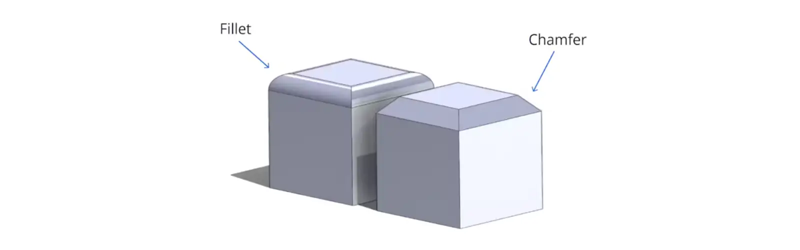
Fillet: A rounded, smooth edge that looks like a radiused arc
Chamfer: A flat, angled cut that looks like a small triangle has been removed from the corner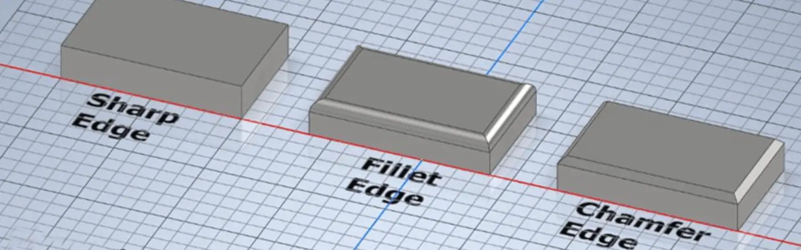
A Fillet is significantly stronger for high stress or fatigue loads. The curved shape smoothly disperses stress, while the chamfer’s straight edges create stress concentration points that can lead to cracking.
Chamfers are generally faster and cheaper. One universal chamfer tool can create many sizes in a single pass, while fillets often require specialized tools and more complex programming.
Choose fillets when:
Choose chamfers when:
You need easy part assembly (acts as a guide ramp)
Yes. While most common on external edges, chamfers can also be applied to internal edges like hole rims for guiding pins or countersinking screws.
This is a physical limitation – round cutting tools naturally create rounded corners. The corner radius will always match the tool radius used.
You have three options:
Corner Cleanup: Using tiny tools (slow, high risk)
EDM: Electrical discharge machining (expensive, adds time)

Dog-Bone Fillet: Design compromise that allows square parts to fit
Visit our blog for more information.
How to Machine Sharp Inside Corners
Most manufacturers use C0.2mm to C0.3mm purely for safety and deburring. Larger chamfers must be specifically specified.
Radius (R): The size dimension (e.g., R5.0)
Fillet: The actual geometric feature
In practice, the terms are often used interchangeably.
Fillet: Universal term for all rounded edges
Round: Specifically refers to external fillets (convex edges)

Geometrically similar, but:
Chamfer: Used for assembly and deburring in machining
Bevel: Used specifically for weld preparation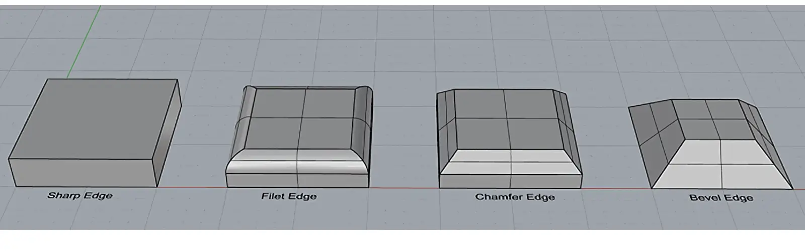
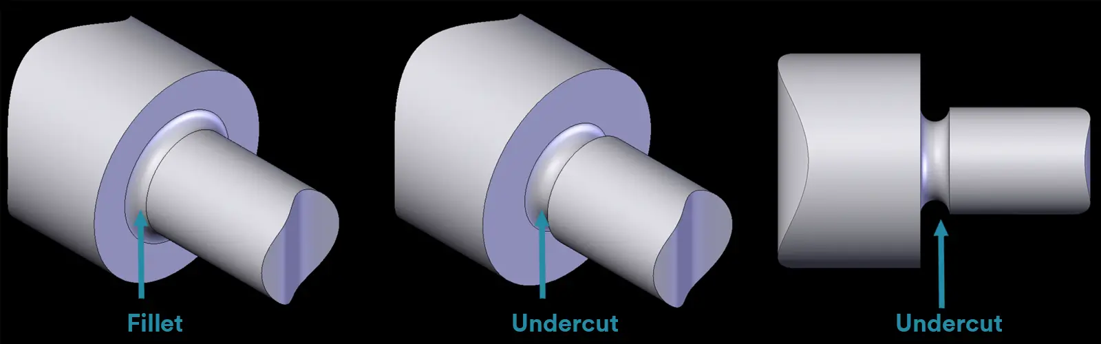
Neither a chamfer nor fillet – it’s a recessed feature cut below the surface to provide clearance for other parts or operations. A Relief Groove is a common type.
An advanced fillet that creates smooth transitions between surfaces meeting at complex angles, often using variable radius.
Add this note to your blueprint: “BREAK ALL SHARP EDGES C0.2 MAX” or “BREAK ALL SHARP EDGES R0.2 MAX”
This tells the manufacturer to quickly remove burrs without complex measurement.
Because chamfers are:
Absolutely! Many parts use fillets in high-stress areas and chamfers for assembly features – this provides the best balance of strength and functionality.
Fillets: Use “R” notation (e.g., R3 for 3mm radius)
Chamfers: Use “C” notation (e.g., C1 for 1mm 45° chamfer) or “Length × Angle” (e.g., 1.5 × 45°)
Worried about breaking? → Choose Fillet
Need easy assembly or lowest cost? → Choose Chamfer

5-Axis CNC machining is a manufacturing process that uses computer numerical control systems to operate 5-axis CNC machines capable of moving a cutting tool or a workpiece along five distinct axes simultaneously.
Sharp corners in CNC machining present a significant design issue. The thing is that no conventional milling or turning process can actually get to shape them correctly because of inaccessible corner geometry.

Selecting the right prototype manufacturing supplier in China is a critical decision that can significantly impact the success of your product development project.

Machining tolerances stand for the precision of manufacturing processes and products. The lower the values of machining tolerances are, the higher the accuracy level would be.