The foremost step to learn about GD&T profile of a line is to know what is it, including its definition and its tolerance zone. In this part, we will particularly provide comprehensive knowledge of the definition and tolerance zone of profile of a line in GD&T.
GD&T profile of a line is a kind of Profile Symbols that is used to control the deviation of any actual linear element on surfaces, like straight lines, curved lines or lines on cross-section planes from their exactly ideal profile.
It is a 2D tolerance that can be applied to any linear tolerance. In short, profile of a line in GD&T functions in confining the curvature of a controlled part as remanded.
What’s more, GD&T profile of a line is a kind of synthetical tolerance that actually controls the form, orientation, location and feature of size, all of which together draw the linear profile.
As GD&T profile of a line confines the variation of the measured linear profile from its ideally theoretical profile, its tolerance zone comprised of two parallel lines(straight or curved) that locate isometrically up or below the ideally designed linear profile ensured through the true position.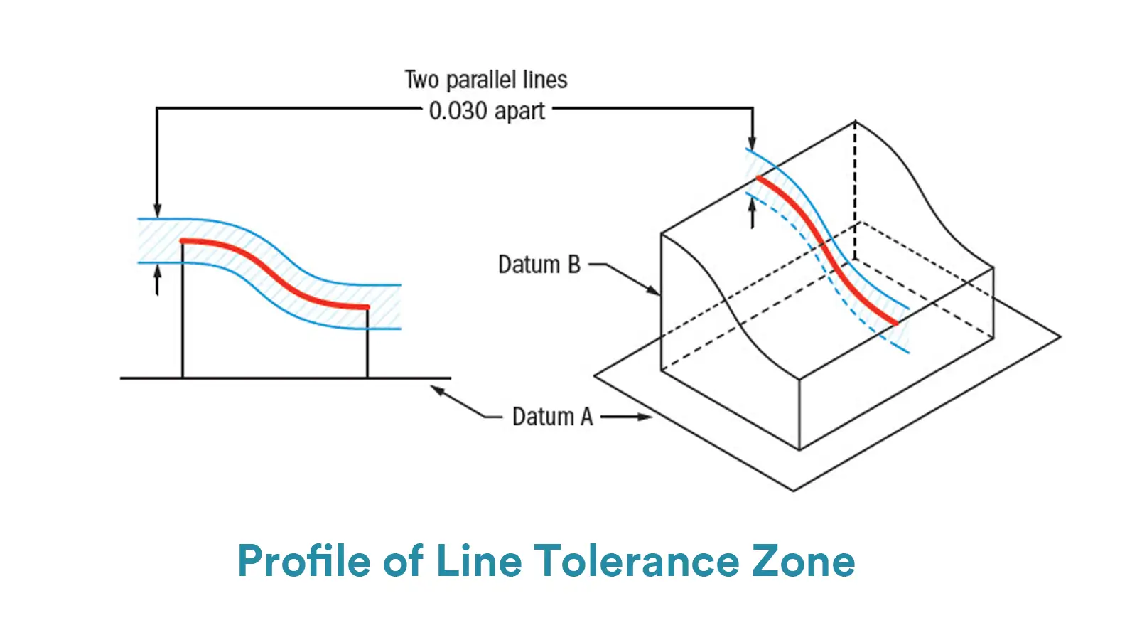
That is to say, the two lines of the tolerance zone are not only parallel to each other, but also both parallel to the true profile, and the respective distance of each point on the two lines to the true profile is the same distance.
Therefore, if the measured profile of a line on the feature want to pass, all points of the measured profile of the line should lie within these two parallel linear profiles and the tolerance value is the distance of these two lines. But note that the permissible deviation is half the tolerance value.
After learning about what is profile of a line in GD&T, we then move towards to learn how to show GD&T profile of a line in engineering drawings.
The feature control frame of profile of a line is simply composed two or three parts. The first one is the symbol of GD&T profile of a line, which is an inverted semicircle. And the second part is the tolerance value, which is the width of the tolerance zone.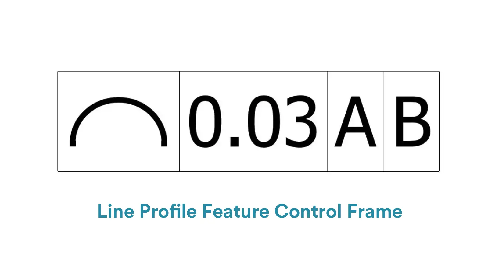
The tolerance zone is a 2D zone composed with two parallel lines distributing bilaterally in relation to the true profile. The third block is the datum symbol(A, B or C) if required.
But pay attention to that GD&T profile of a line can use datums as reference or not use datums. If no datum is referred, GD&T profile of a line is simply used to paly as a form control like GD&T Straightness and GD&T Circularity.
However, if it is used with datums, GD&T profile of a line controls not only the form, but also the orientation and location by fixing the exact position of the tolerance zone with respect to the datum line profile.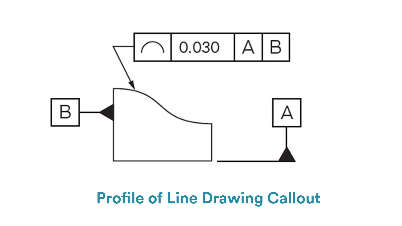
And note that GD&T profile of a line is not compatible with material modifiers.
In engineering drawings, the feature control frame of GD&T profile of a line is usually connected with a leader arrow directly pointing to the edge line of the measured profile.
And if the measured profile is controlled by theoretically exact dimension, the feature control frame of GD&T profile of a line is usually connected with a leader arrow pointing to the dimension line.
More importantly, it is required that the GD&T profile of a line must be indicated in the view where the measured profile is clearly shown.
In this part, we will provide comprehensive guides of measurement procedure for GD&T profile of a line. What’s more, we will also list their respective advantages and disadvantage for your convenience to select the most proper means in measurement.
We have mentioned coordinated measuring machines(CMMs) many times before. CMMs are automate machines suitable for many GD&T tolerance measurements.
For GD&T profile of a line measurement, CMMs are advantage in high accuracy and ability to generate visual deviation reports. However, they are disadvantage in high equipment cost and sensation to environment. Below is the detailed guide for GD&T profile of a line measurement by this means: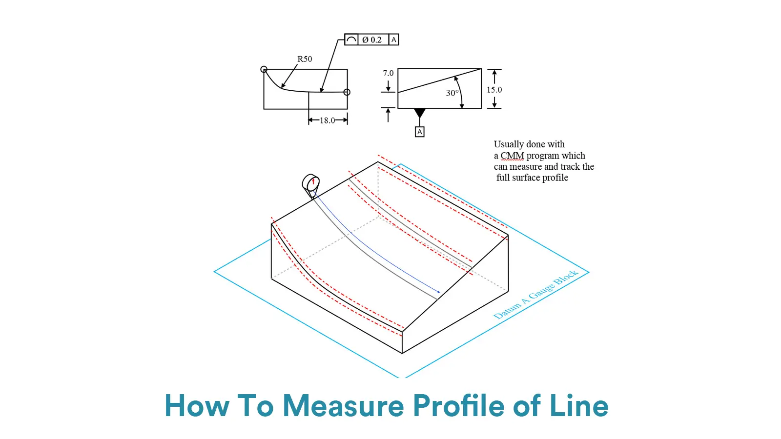
Firstly, fix the measured feature on the CMM table and establish the coordinate system.
Secondly, use the probe to densely sample points along the contour. The point spacing depends on accuracy requirements.
Thirdly, use the CMM software to compare the sampled points with the theoretical CAD contour and then calculate the profile deviation.
Profile projector is one of the most common tools for GD&T profile of a line measurement. Their measuring procedures are simple and fast, and the measuring result is intuitive. Profile projectors are suitable for simple 2D profiles measurement with low cost and easy operation.
However, they rely on manual interpretation, which means that the measuring results would be affected easily by subjective elements. And they are only suitable for thin-walled or 2D profiles with limited accuracy. Below is the detailed guide for GD&T profile of a line measurement by this means:
Firstly, place the measured feature on the projector stage, ensuring the measured profile perpendicular to the light axis of projector, and adjust magnification to ensure proper accuracy. And then adjust the brightness and contrast of light source to ensure clear imaging of the measured contour.
Secondly, move the stage or rotate the measured feature to keep the profile clearly projected on the green, and then overlay the projected contour with the standard template for comparison.
Thirdly, calculate the deviation via software or simply analyze the deviation visually.
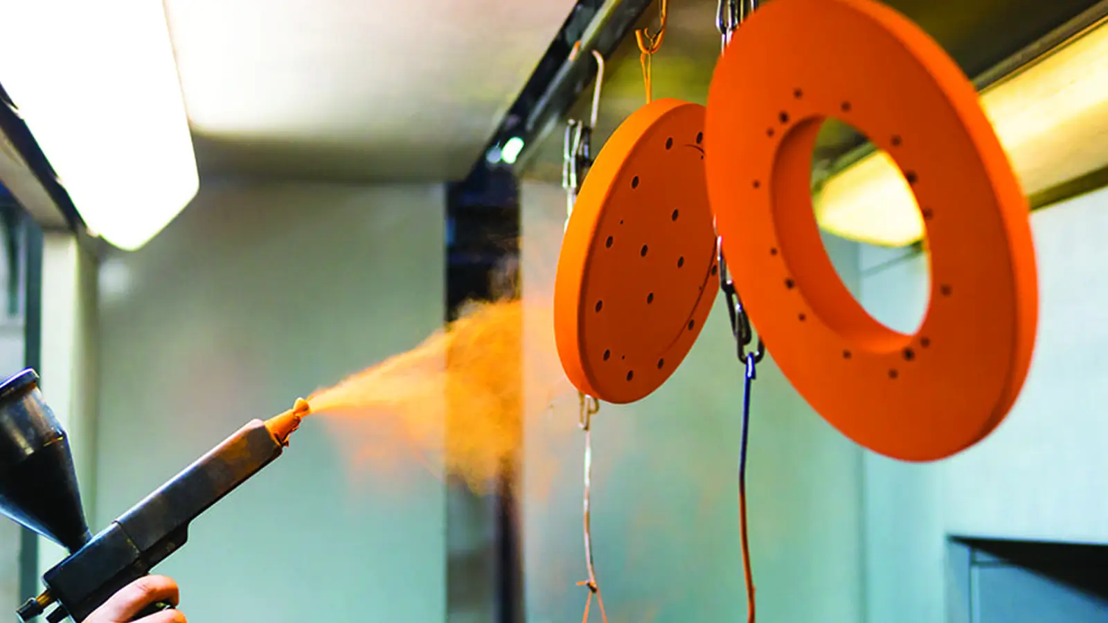
Laser scanner is suitable for flexible or fragile parts due to its non-contact measurement. Expect that, laser scanner is also suitable for large-size profiles profiting from its fast-scanning speed.
However, since laser scanner is susceptible to surface reflectivity or color, contrast spray may be required during measurement. And the equipment is expensive. Below is the detailed guide for GD&T profile of a line measurement by this means:
Firstly, align the laser scanner and fix the measured feature steadily on the plate.
Secondly, operate the laser scanner to scan along the contour to obtain the cloud data of points.
Thirdly, fit the cloud data of points to the CAD model to calculate the profile deviation.

GD&T profile of a line is to control the deviation of any actual linear element on surfaces, like straight lines, curved lines or lines on cross-section planes from their exactly ideal profile.

Symmetry controls that the Median Plane of a non-rotating feature must be aligned with the Datum Center Plane. It has been removed from the standard GD&T toolbox.

Concentricity is a position tolerance that measures the degree to which the center points of circular features (cylinders, cones, spheres) coincide relative to a shared datum axis or point.

True position GD&T is one of the position symbols in GD&T that is used to control the positional accuracy of a feature of size, such as a hole, shaft or slot, with respect to the datum coordinate system.