According to applications, straightness can be classified into three types. The first is that used on 2D dimension, like on edges or surfaces. While the second one and the third one are that used on 3D dimension, mainly on axes and derived median lines.
Though the basic definition of straightness is the same, its tolerance zones and measurements differ much from each other based on the classification.
Surface straightness in GD&T is generally used on flat or cylindrical surfaces. It controls the bending extent of the measured line in a designated plane for flat surfaces, commonly refining the straightness of edges, profiles or section lines.
In such cases, the tolerance zone is the area of two parallel lines that above and below the ideal position and the tolerance value is the distance of these two lines. See the GD&T straightness examples below.

For cylindrical surfaces, GD&T straightness is used to control the deviation of the measured line along a specific direction in 3D space, commonly restraining the straightness for generating lines of cylinders or cones.
In such cases, the tolerance zone is the area of two parallel lines or planes that along the specific direction. That is to say, the projected line in the designated direction must lie within the tolerance zone. The tolerance value is also the distance of the two parallel lines or planes. Check GD and T straightness symbol below.

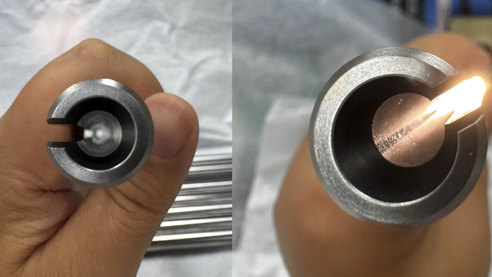
The second function of GD&T straightness symbol is to control the straightness of a cylinder’s axis, which is essential for required assembly and operational accuracy.
Different from surface straightness, it does not control the surface form, but controls the actual axis of cylinders. And the tolerance zone is a cylinder instead of two parallel lines.
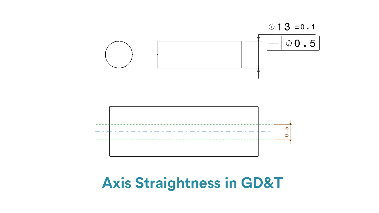
What’s more, the tolerance value is the diameter of the cylinder where the measured axis can be within. But note that the allowed deviating scope is the radius of the cylinder.
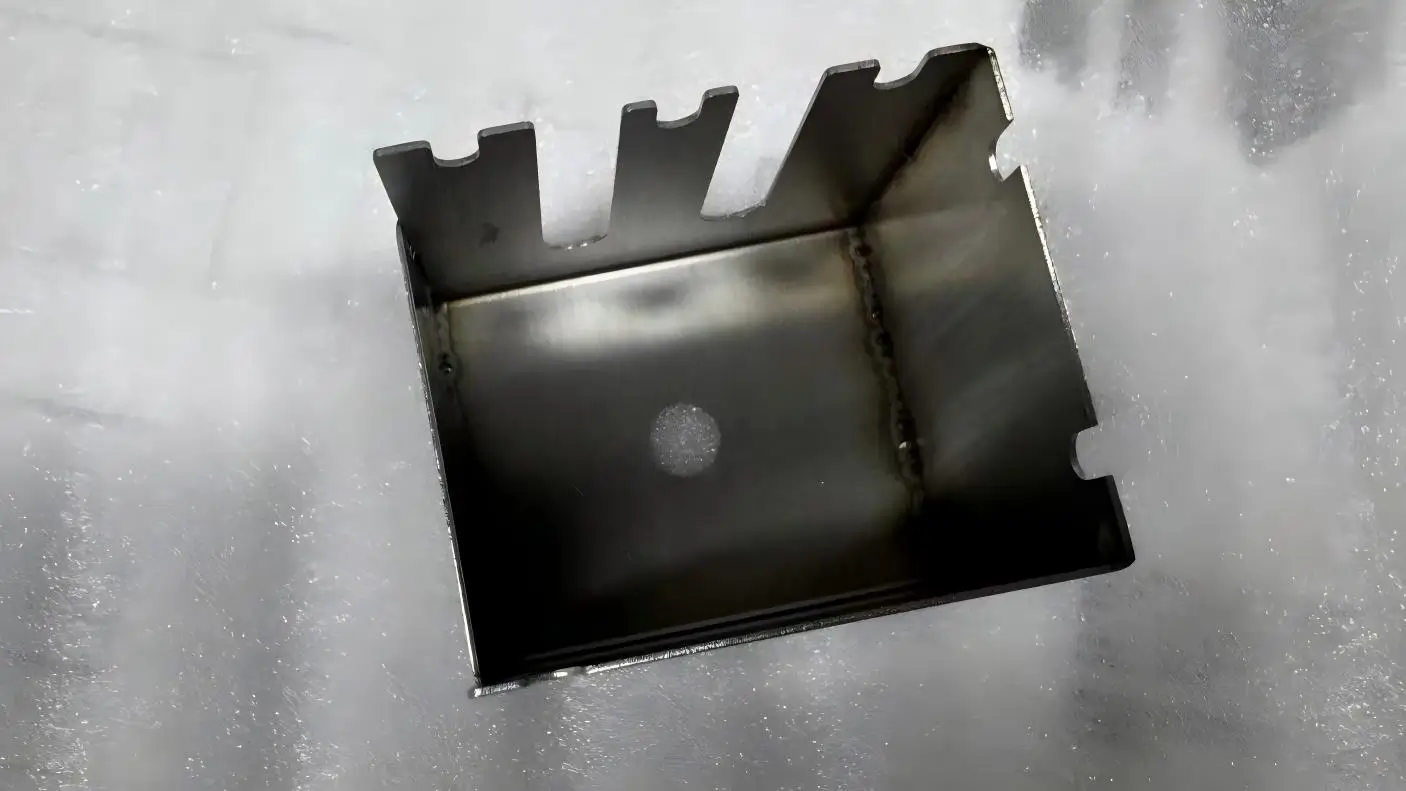
The derived median line(DML) is also a kind of axis. The essential difference is that it is the hypothetical axis of a part with axisymmetric features, like a trough or a nonideal cylinder.
When applied to a nonideal cylinder, the tolerance zone of DML straightness is a perfect cylinder around the true axis of the part. While for a trough, the tolerance zone is the area of two parallel lines along the specific direction.
And note that the DML straightness is required to apply only along one direction, so the surface could be curved or irregular in the other orthogonal direction, which is different from the derived median line for flatness.

The straightness symbol in GD&T is simply a flat, horizontal line like a hyphen. However, since GD&T straightness would vary according to its application, the callouts are different from each other without doubt.
 Below we will list the particular callouts under different circumstance.
In 2D dimension, like surface straightness or derived median line straightness for a through, the callout is comprised of simply the line symbol and tolerance value. The feature control frame is directly connected with the measured surface by a leader pointing arrow.
In 3D dimension, like axis straightness and derived median line straightness for a nonideal cylinder, the composition of feature control frame is more complex. The callout consists of straightness symbol, diameter symbol and tolerance value, as well as material modifiers if required.
In addition, compared with surface straightness, the leader arrow of axis straightness does not point to the surface, but marks the size dimension for feature of size.
The measuring tools for straightness is various in engineering. Based on the application of straightness, the main measurement tools include height gauges, dial gauges and coordinate measuring machines.
Here we will teach you how to measure straightness step by step with these tools. More importantly, their respective advantages and using remarks would also be provided.
A height gauge is commonly used for surface straightness measurement. By moving the probe, the operator collects data of multiple points and then fit a reference line to calculate deviations.
It advantages include high efficiency and good applicability for long features, but it relies on high accuracy platform and can’t measure axis straightness directly. The detailed steps are as follows:
Firstly, calibrate the height gauge and ensure the value be zero.
Secondly, place the measured feature on the flat measuring platform and then fix the feature by clamps or blocks, ensuring the measured edge or line parallel to the platform(adjusting with a square if needed).
Thirdly, mark measurement points along the line(spacing even depending on length and accuracy requirements) and then move the gauge probe to these points to record readings. Note to avoid tilting the probe or pushing excessive force.
Finally, subtract the reading value from the reference value to evaluate the straightness by summing the absolute values of the largest positive and negative deviations. If the final value lies within the required tolerance zone, the measured feature passes.
Dial gauges are a kind of popular tools for straightness measurement. The advantages include lower cost and high flexibility, as well as applicability for both surface straightness and axis straightness, while the disadvantages are lower efficiency and limited measuring ranges.
The detailed steps are as follows:
Firstly, mount the dial gauge on a stand, zero the short dial, align the long needle to the middle, and check spring responsiveness.
Secondly, fix the measured feature and reference. The particular steps differ for different straightness. To measure surface straightness, operators should place the feature on the platform directly with the measured surface up and make the probe of dial gauge perpendicularly contact with the measured surface(the platform serving as the datum).
While to measure axis straightness, operators should support the shaft by V-blocks or rotary fixtures and then make the probe of dial gauge radially contact the cylindrical surface.
Thirdly, record and measure the data. For surface straightness, define the measurement path on the measured surface and move the dial gauge to record the deviations along the line.
For axis straightness, mark the length of the axis by segment, rotate 360° at each segment and then record the radial runout. Note to control the force and measure multiply.
Finally, calculate the straightness. For surface straightness, the deviation value is the absolute value from the crest to the trough. While for axis straightness, it needs to simulate the actual axis by geometrical algorithm with data for radial runout of multiple cross-sections.
And then calculate the deviation from the actual axis to the ideal axis. If the deviation lies within the tolerance zone, the feature passes.
Compared with the above two methods, CMMs are more automate and accuracy for measurement. They are often used to measure axis straightness. But they cost much higher and require tight environment condition.
The detailed steps are as follows:
Firstly, calibrate the CMM probe and select a stylus with proper size.
Secondly, fix the measured feature on the platform of CMM, avoiding vibrating or distorting.
Thirdly, align the coordinate system based on datum features and mark the measured points evenly, ensuring the consistency between measuring path and theoretical direction.
Fourthly, operate the stylus to contact the measured points and record the data. And then simulate the ideal axis by CMM software.
Finally, calculate the deviation. If the value lies within the tolerance zone, the feature passes.

5-Axis CNC machining is a manufacturing process that uses computer numerical control systems to operate 5-axis CNC machines capable of moving a cutting tool or a workpiece along five distinct axes simultaneously.

China is the best country for CNC machining service considering cost, precision, logistic and other factors. Statistical data suggests that China emerges as the premier destination for CNC machining.

Selecting the right prototype manufacturing supplier in China is a critical decision that can significantly impact the success of your product development project.

Machining tolerances stand for the precision of manufacturing processes and products. The lower the values of machining tolerances are, the higher the accuracy level would be.