The premium step is to know what is parallelism GD&T, including its definition, callout and tolerance zone. They are the basic but essential information of parallelism GD&T.
Parallelism GD&T is a kind of orientation tolerance used to ensure that the reference surface or axis is parallel to the datum surface or axis.
That is to say, parallelism GD&T controls a condition where all points on a surface or axis is equidistant from a datum surface or an axis.
From the above information, it is obvious that there are two types of parallelism in GD&T. It is classified into surface parallelism and axis parallelism.
Both of them is aimed to maintain parallelism, to say, 0° alignment with the datum element according to the limits specified in the feature control frame. However, the surface parallelism is much more commonly applied in engineering and manufacturing.
Based on the different types of parallelism, the tolerance zones are different.
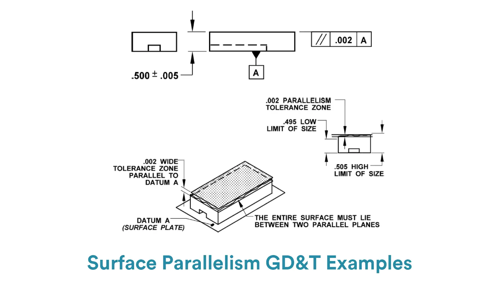
For surface parallelism, the tolerance zone consists of two perfectly theoretical parallel planes. And both of these two planes are parallel to the datum surface or axis. It controls that all points on the planar surface or center plane of the measured feature must lie within the two parallel planes.
And the tolerance value is the perpendicular distance between the two parallel planes.
According to the shape of the tolerance zone, it is obvious that the parallelism tolerance is not an angular tolerance zone to control the 0° alignment between the controlled surface to the datum plane but a tolerance zone at a 0° angle.
At the same time, the permissible deviation is controlled by widening or tightening the perpendicular distance of the two parallel planes.
For axis parallelism, the tolerance zone is a perfect cylinder whose central axis is parallel to the datum axis. It controls that the axis of a feature of size like a cylindrical pin or a hole is parallel to the datum element.
That is to say, all the points of a passed feature’s central axis must lie within the cylinder. And the tolerance value is the diameter of the cylinder.
Therefore, different from surface parallelism, axis parallelism creates an angular tolerance zone and the permissible angular variation can be controlled by changing the diameter of the cylinder.

For surface parallelism, the feature control frame consists of three parts. The first part is the GD&T symbol of parallelism, which is comprised of two oblique parallel lines. The second part is the tolerance value, which is the perpendicular distance of the tolerance zone. And the second part is the datum block.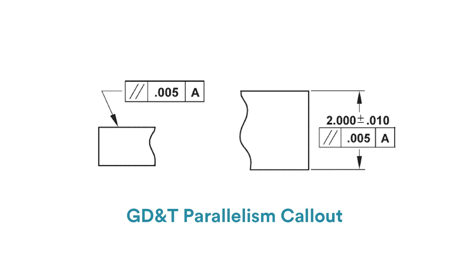
For axis parallelism, the main difference focuses on the tolerance block and the material modifier block. Same as the surface parallelism, the first part is the GD&T parallelism symbol.
While the second part consists of the diameter symbol and the tolerance value, which means that the tolerance value is the diameter of the cylindrical zone.
In addition, axis parallelism can be used with material modifiers like MMC and LMC. And the final part is also the datum.
Besides of the composition of feature control frame, the GD&T parallelism callout is also related to the controlled feature. Depending on the intended use, a parallelism feature control frame may be applied to a surface or a feature of size.
When used on a surface, the feature control frame may point to the measured surface itself or attach to an extension line of the surface by a leader arrow. While when used on a feature of size, it may be placed with the size dimension.
Note that normally the parallelism confirms only a datum reference, but in some cases a secondary datum may be used. While a tertiary datum is not generally used with parallelism control.
More importantly, pay attention to that due to the envelope principle, the parallelism tolerance must be smaller than the size tolerance.
The measurement of GD&T parallelism is a crucial part in manufacturing and inspection. Particularly suitable measuring methods should be elected depending on different requirements for accuracy level and component types. Here we list the common tools for parallelism measurement with their respective pros and cons.
A dial gauge with surface plate is one of the most common methods for parallelism measurement. It is particularly suitable to measure surface parallelism of small or medium parts, and stands out for simple operation and low cost. But the measuring accuracy of this method is limited, typically ±0.01mm. Below is the specific steps for parallelism measurement by this method:
Firstly, securely place the measured feature on the inspection surface place with the datum surface down, directly attaching to the plate.
Secondly, fix the dial indicator to a height gauge or a magnetic stand, adjusting the probe to contact the measured surface, and then zero the dial indicator on the datum surface.
Thirdly, select multiple(typically 5-9) points of the measured surface and move the dial indicator to measure those points.
Finally, record the data at each point and figure out the deviation of parallelism. If the difference between the max and min values is smaller than the tolerance value, the measured feature passes.
A dial gauge with V-block is a common method for axis parallelism measurement. It stands out for simple operation and low cost. While its disadvantages include that it is only suitable for rotationally symmetric features and its accuracy is hugely affected by V-block precision. Below is the specific steps for parallelism measurement by this method:
Firstly, steadily fix the datum axis on V-blocks.
Secondly, touch the dial indicator probe to the measured shaft’s surface and rotate the datum axis to minimize radial runout, ensuring good contact with V-blocks.
Thirdly, move the dial indicator along the shaft length and record data at multiple positions.
Finally, calculate the deviation of parallelism. If the difference between the max and min readings is smaller than the tolerance value, the measured feature passes.
Besides GD&T Straightness, GD&T Flatness, GD&T Circularity and GD&T Cylindricity that we have produced before, GD&T Parallelism can also be measured by coordinate measuring machines.
CMMs can measure both surface parallelism and axis parallelism. And CMMs are suitable for complex features with high accuracy requirements.
However, the equipment is expensive and needs high maintenance cost. Below is the specific steps for parallelism measurement by this method:
Firstly, measure datum features(plane or axis) to set up the coordinate system.
Secondly, record data of multiple points along the measured element of the feature.
Thirdly, use CMM software to auto-calculate the parallelism deviation.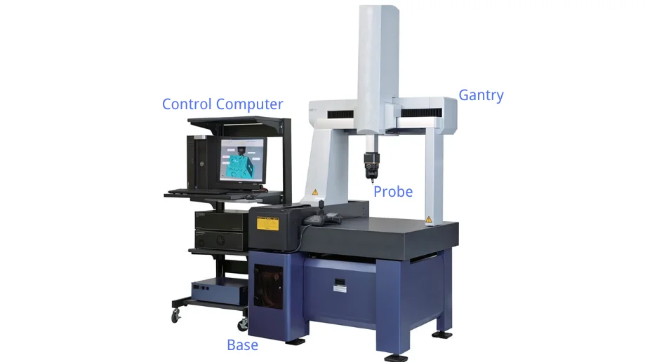
Finally, determine pass or fail by comparing the deviation with the tolerance value.


Cylindricity is to control the overall deviation of a cylindrical surface from a perfect geometric cylinder.

Parallelism GD&T is to ensure that the reference surface or axis is parallel to the datum surface or axis.

Perpendicularity GD&T is used to control the measured surface or axis, keeping 90° with the datum surface or axis.

GD&T angularity GD&T is used to control a particular angle between the specified feature and the datum feature