Home » Blog » Total Runout in GD&T

Total Runout in GD&T Explained

By Lucas Lo | Updated: May 27, 2025

Table of Contents

    In engineering, runout refers to the deviation of a rotating feature produced when rotating around a central axis. Machines should minimize any wobble or eccentric rotation as much as possible, since that would cause problem during the functioning process. That is where the GD&T Runout tolerances come into play.

    GD&T runout symbols consist of circular runout GD&T and total runout GD&T. We have introduced circular runout GD&T in the previous article. And we will explain total runout GD&T in details below.

    1. What is Total Runout in GD&T?

    In this part, we will talk about what is total runout in GD&T, including the definition and tolerance zone.

    1.1. Total Runout GD&T Definition

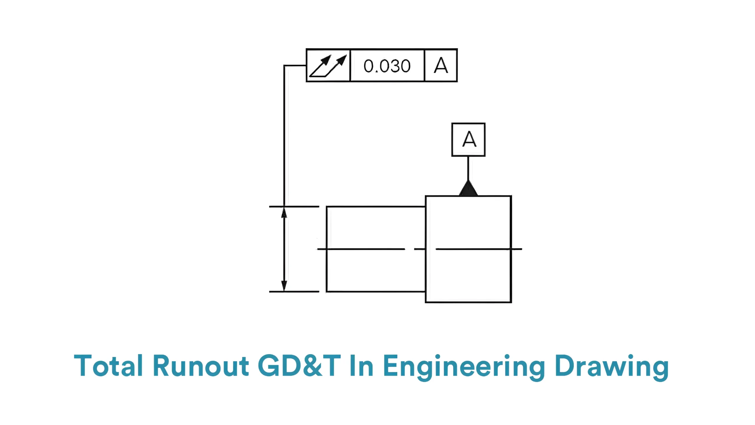
    Total runout GD&T is one of the runout symbols that mainly controls the runout deviation of the measured feature’s entire surface during rotation around the datum axis.GD&T Total Runout Symbol

    Controlled by total runout GD&T, the runout dimension of all points on the feature’s surface must be smaller than the tolerance value indicated on the engineering drawings.How to Callout Total Runout-Picsart-AiImageEnhancer

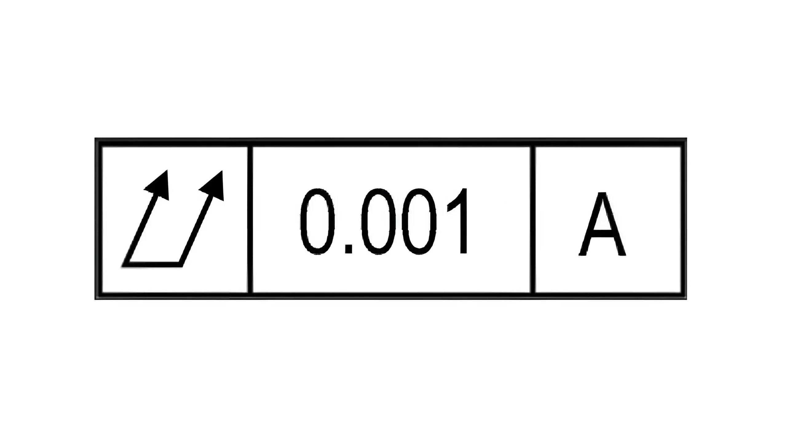
    What is more, it is a synthetical tolerance that controls both the radial runout of the entire measured surface and the runout deviation in the axial dimension.

    In short, when a feature is rotating around the central axis, both the radial runout and the axial runout should be controlled within the same tolerance according to the total runout GD&T.

    And confining the runout variation of the entire surface means to confine the cylindricity location and orientation of the measured feature at the same time.

    1.2. Total Runout GD&T Tolerance Zone

    The tolerance zone of total runout can be classified into two types based on the different controlled elements.Total Runout Tolerance Zone

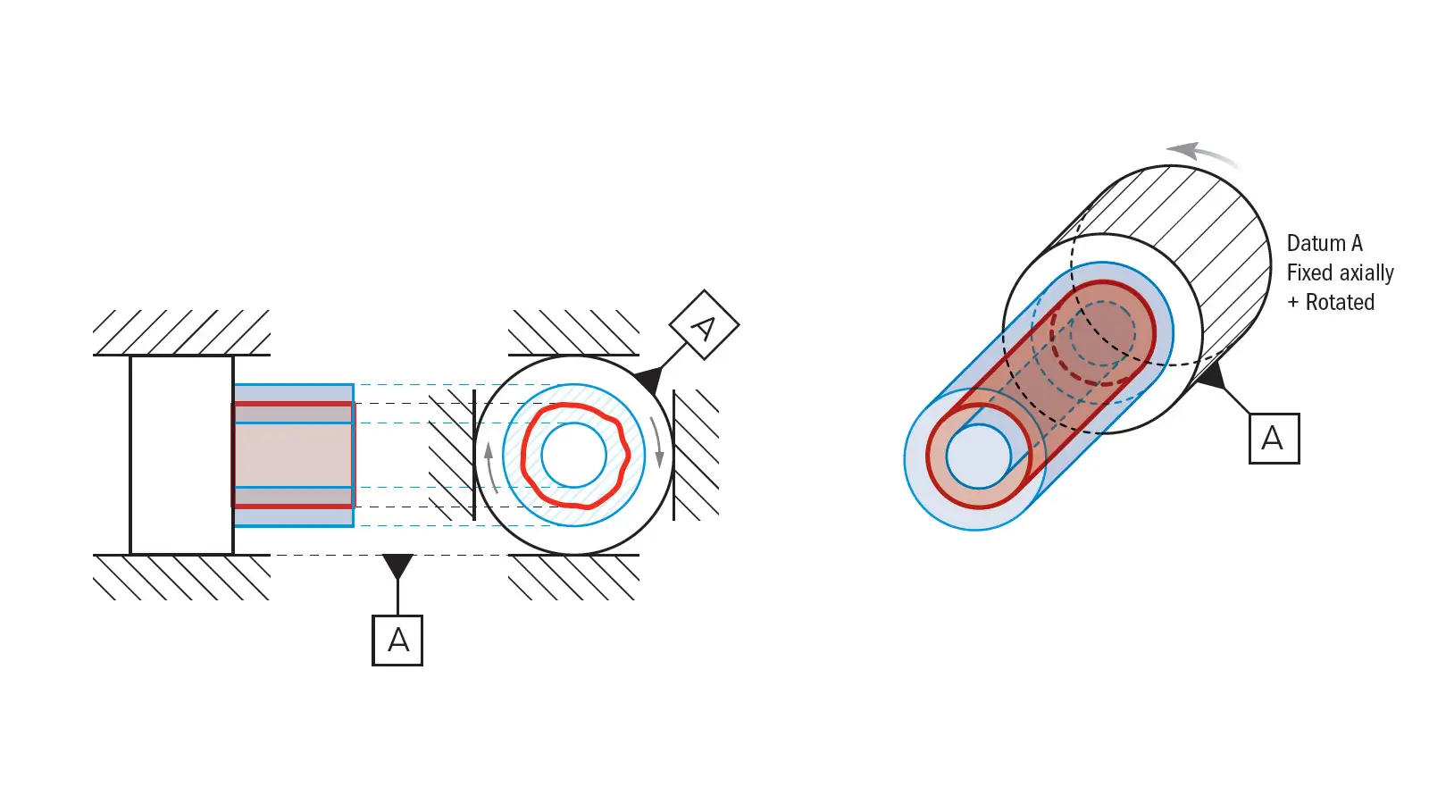
    The main one is the radial total runout tolerance zone, which consists of two cylindrical planes.

    These two cylindrical planes are coaxial with the datum axis. The tolerance value is the distance between the two cylindrical planes, which refers to the maximum permissible runout deviation of the measured feature(usually the entire cylindrical surface).

    If a feature is manufactured to pass the total runout GD&T, the entire surface must runout with a smaller dimension than the tolerance value, which means all the points on the cylindrical surface of the measured feature must lie within the zone of these two cylindrical planes, when the feature is rotating around the central axis.

    By confining the runout of the cylindrical surface within the two coaxial cylindrical planes, radial total runout tolerance effectively controls the circularity, cylindricity and co-axiality of the actual cylindrical surface.

    Thus, the vibration during rotation is effectively reduced.

    The other one is the axial total runout tolerance zone, which is composed with two parallel planes that are both perpendicular to the datum axis.

    The controlled element of axial runout is usually the head or end face of the measured part. Both the head surface and the end surface are designed to be perpendicular to the datum axis.

    The tolerance value is the perpendicular distance between these two parallel planes, which is the maximum permissible runout deviation along the axial direction during the rotation.

    But note that the tolerance value of radial runout is similar to that of the axial runout. It means that radial runout and axial runout are controlled at the same time by one total runout tolerancing indication on the engineering drawing.

    Controlled by axial runout tolerance, all points on the head or end surface of the measured part must lie within the two parallel planes that are perpendicular to the datum axis.

    The flatness and perpendicularity of the head and end surfaces are controlled at the same time.

    2. How to Show Total Runout GD&T Callout?

    The total runout GD&T callout indicates the information mainly by the feature control frame. The feature control frame of total runout GD&T is comprised with three blocks.

    The first block shows the information of the geometric characteristic GD&T symbol.

    For total runout GD&T, it is a symbol of two arrows that parallelly point to the northeast and are connected by a horizontal line at the bottom, meaning that the runout across the entire length is controlled by the total runout GD&T.

    The two arrows refers to the total runout that is measured from one end of the part to the other. And the horizontal line stands for the entire surface under control.

    The second block shows the information of feature tolerance, including the tolerance zone and the tolerance value, as well as the material condition modifiers if applicable.

    For total runout GD&T, this block contains only the tolerance value. Since the tolerance zone of the total runout GD&T is not diametral, there is no diameter symbol in this block.

    And total runout GD&T controls a feature without a material condition modifier all the time. It is always applied RFS(Regardless of Feature Size).

    The third block shows the information of datums. Total runout GD&T must select at least one reference as the datum.

    Simple features usually refers to the central axis as the only one datum. While for complex features like a shaft with multiple diameter dimension, multiple datums may be referred to.

    They are shown independently within different blocks of the feature control frame, as primary datum, secondary datum and tertiary datum etc.

    And then the feature control frame would be connected with an arrow that directly points to the measured feature in the engineering drawing. Or it can also point to the extension line of the measured feature.

    3. How to Measure Total Runout GD&T?

    Dial indicators and CMMs(Coordinate Measuring Machines) are two kinds of common tools for total runout measurement. The former relies more on manual operation while the latter is more automated. The concrete operational steps are as follows:

    3.1. Using Dial Indicator to Measure Total Runout GD&T

    Step 1: Clean the measured feature and measuring equipment. Ensure the measured surface, reference axis, and dial indicator probe are free from oil, burrs, or damage.How to Measure Total Runout with Dail Gauge

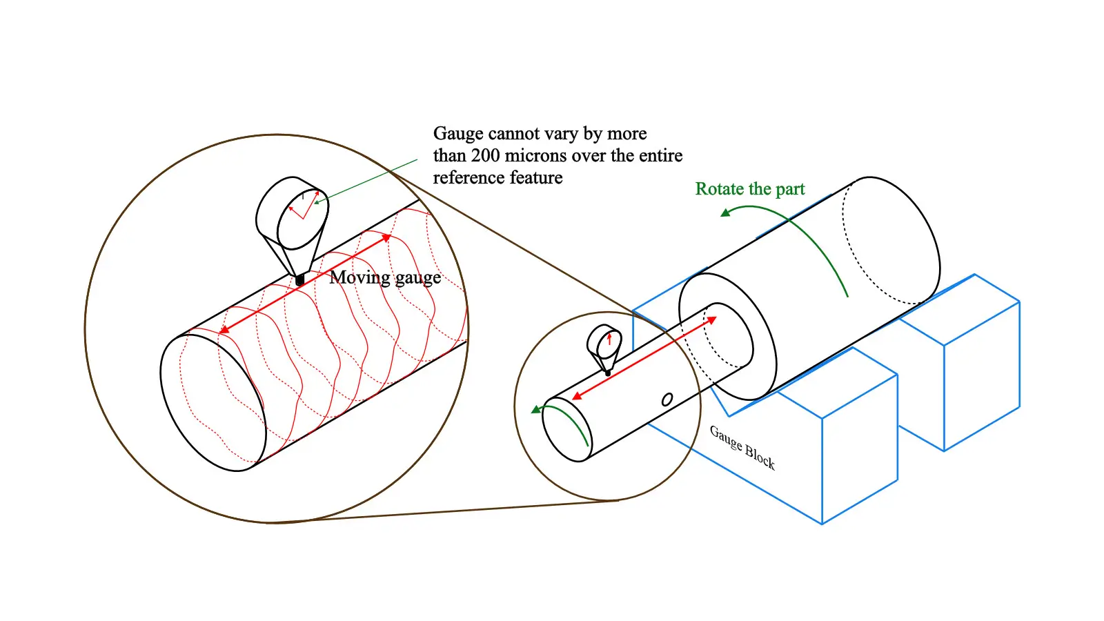
    Step 2: Fix the dial indicator on a magnetic stand or rigid bracket steadily. And then fix the measured feature between two coaxial center(for shafts) or on V-blocks(if no center hole is there), ensuring free rotation around the datum axis.

    Step 3: Measure the radial total runout. Contact the dial indicator probe perpendicularly against the middle of the cylindrical surface with a preload of 0.1-0.3mm(1/2 to 1 full turn). And then slowly rotate the part one full turn.

    Record the difference between max and min readings, which is the circular runout of one single cross-section.

    Note to move the dial indicator axially along the entire length to measure multiple cross-sections and record the largest variation of these sections, which is the final radial total runout.

    Step 4: Measure the axial total runout. Contact the dial indicator probe perpendicularly against the edge of the end face. Rotate the part one full turn and record the difference between max and min readings.

    Note to move the probe radially to cover the entire face and record the largest variation of the end face, which is the final axial total runout.

    Step 5: Compare the actual total runout with the tolerance value. If the variations of radial total runout and axial total runout are both smaller than the tolerance value, the measured part passes.

    3.2. Using CMMs to Measure Total Runout GD&T

    Step 1: Clean the measured surface and datum axis. And then fix the measured part firmly on the CMM table, aligning it with the datum axis by V-blocks or other fixtures.

    Step 2: Select an appropriate probe and calibrate it to ensure the measurement accuracy. Measure the cylindrical surface to fit a centerline as the datum axis. Then set the datum axis as the Z-axis and define the XY-plane origin.

    Step 3: Measure continuously or in layers along the target surface.

    Step 4: Use the CMM software to output the final deviation automatically.

    4. Total Runout VS Circular Runout VS Cylindricity

    Actually, total runout GD&T is a synthetical tolerance that controls various geometric elements at once. Circular runout GD&T and cylindricity GD&T are the two that would mostly be confused with total runout GD&T. Here we will distinguish the difference among them.

    4.1. Total Runout GD&T VS Circular Runout GD&T

    Circular runout GD&T is similar to total runout GD&T to some extent. They are both synthetical runout tolerance that controls form, orientation and location at the same time. But there is key difference between them.

    Total runout tolerance controls the entire surface along the length while circular runout controls the specific cross-section(part of the surface) at a time.

    And the tolerance zone of the total runout GD&T can be seen as the 3D version of the tolerance zone of circular runout GD&T.

    Circular runout GD&T controls the runout of a single cross-section with respect to the datum axis during rotation.

    The tolerance zone of it is the ring area between two concentric circles whose centers are both the intersection of the measured cross-section and the datum axis.

    Total runout GD&T controls the runout of an entire cylindrical surface referring to the datum axis during rotation.

    The tolerance zone is composed with two cylindrical planes whose central axis are both the datum axis.

    Total runout cost more on measurement than circular runout.

    Below is the comparison table of total runout and circular runout.

    ItemCircular RunoutTotal Runout
    Control AreaSingle cross-sectionEntire surface or length
    Controlled FeaturesRoundness + CoaxialityRoundness + Straightness + Cylindricity + Coaxiality
    Tolerance LevelLower precision requirementHigher precision requirement
    Typical ApplicationsBearing seats, localized shaft controlSpindles, rollers, precision rotary parts

    4.2. Total Runout GD&T VS Cylindricity GD&T

    Total runout is a runout tolerance that needs to take a datum axis as reference while cylindricity runout is a form tolerance that focuses only its theoretical form, not needing datums.

    Cylindricity GD&T controls the deviation from the entire measured cylindrical surface to the theoretical cylinder. It does not care the specific centers of different cross-sections.

    Total runout controls the runout variation of the measured feature during rotation around its datum axis. It controls not only the cylindrical form, but also the orientation and location of the measured feature.

    Their tolerance zones are certainly similar, both comprised of two perfect cylindrical planes.

    The different it that the two cylindrical planes of total runout tolerance zone must be coaxial with the datum axis while that of cylindricity GD&T can be any theoretical cylindrical planes; the axis is beyond control.

    5. Conclusion

    Total runout GD&T controls the geometry very tightly. It is usually applied into high-speed rotating parts. A low total runout can effectively reduce vibration, oscillation and noise during rotation.

    This article has provided comprehensive guide of total runout GD&T. But if you still have any confusion about it, please contact us freely.

    Lucas

    Lucas is a technical writer at ECOREPRAP. He has eight years of CNC programming and operating experience, including five-axis programming. He also spent three years in CNC engineering, quoting, design, and project management. Lucas holds an associate degree in mold design and has self-taught knowledge in materials science. He’s a lifelong learner who loves sharing his expertise.

    Learn More about Lucas.

    Let's get your projects started, together!

    Get custom parts machined in high quality, delivery on time.