Circularity is one of the GD&T Symbols in engineering and manufacturing, because GD&T circularity is an internationally standardized symbol in industries, hugely functioning in uniform form control of features.
Therefore, it is supposed to get comprehensive knowledge of it and learn to use it correctly. In this section, we will explain what is GD&T circularity and how to show it in engineering drawings in details.
GD&T circularity is one of the important symbols in geometric tolerances, mainly used to control the deviation level from the actual circular profile to the ideally perfect circle.
Served as a from tolerance, circularity refers to the acceptable deviation from the actual form of any cross-section of cylinders, cones and spheres, to the idea circle.
Since circularity restraints the varying rage of the actual profile of the measured circle along the radii direction, the tolerance zone of circularity is an annulus comprised with two concentric circles.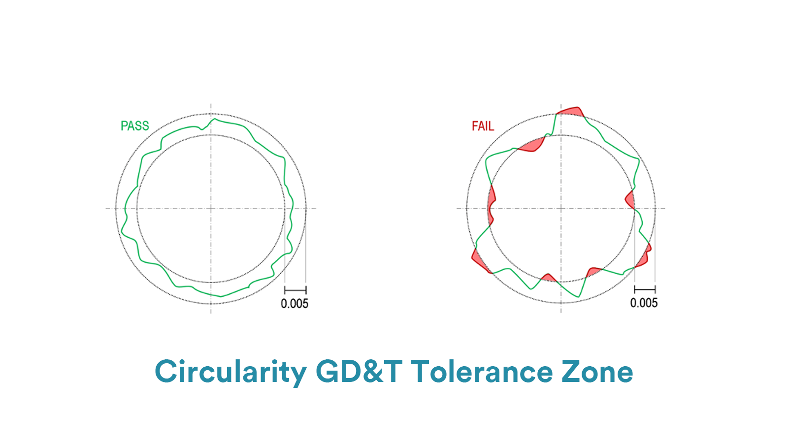
These two concentric circles lie on a plane that is perpendicular to the central axis of the measured feature, and the center of them is that of the measured feature’s axis.
The measured cross-section must lie within the annulus, and the tolerance value is the difference between the radii of the two circles.
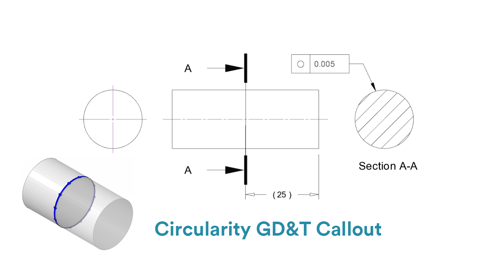
The symbol of GD&T circularity is particularly a circle. And because circularity refines only the form of circle itself, it is independent from datum and material modifiers, which means that callouts of circularity are simply comprised with the circularity symbol and tolerance value.
The feature control frame points to the surface of the measured feature by a leader arrow, controlling the circularity of every cross-section from the feature.
Common tools for circularity measurement mainly include roundness testers, height gauges and coordinated measuring machines. We will provide detailed operating procedure of these tools below:
Roundness testers are suitably applied to features with requirements for high-accuracy measurement. The measuring accuracy of roundness measuring machines can get to 0.01μm. But the cost to maintain the machines are certainly high.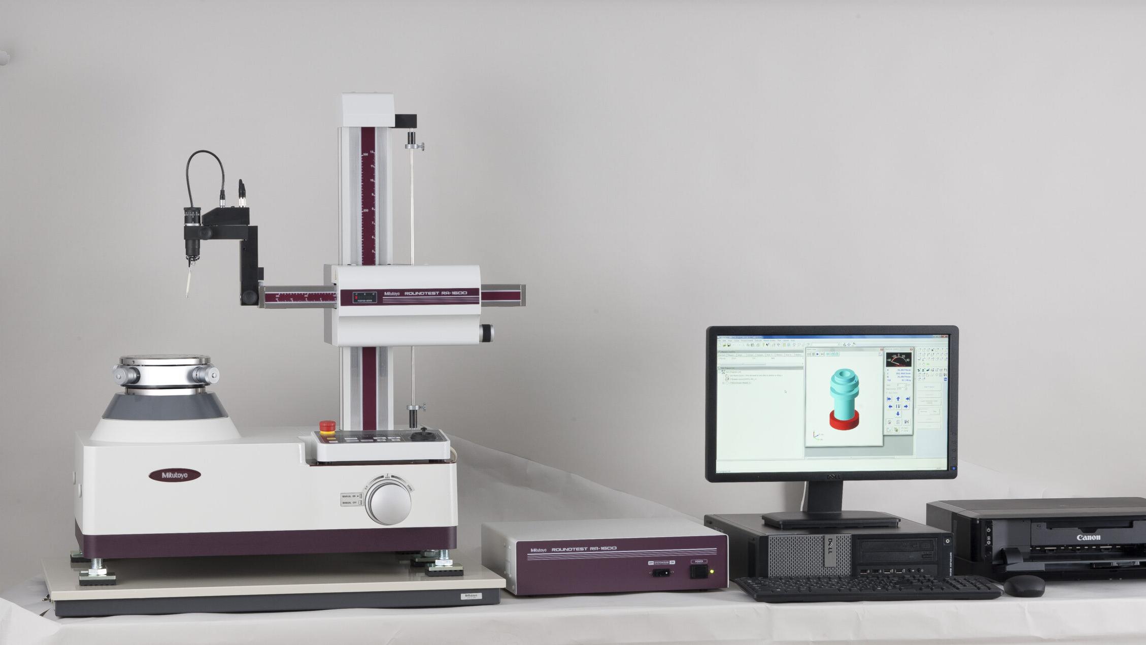
The measuring steps are as follows:
Firstly, fix the measuring part on the rotating spindle or V-blocks, ensuring the axis is concentric with the spindle.
Secondly, gently touch the surface of part with a ruby probe (measuring force typically 0.1–1 N).
Thirdly, rotate the spindle at a constant speed (1–10 RPM) and collect ≥1024 points per circumference.
Finally, record the data and figure out the deviation value by algorithms like Minimum Zone Circle (MZC) and Least Squares Circle (LSC).
The former one refers to two concentric circles enclosing the actual profile, with the minimum radial separation representing the circular deviation(compliant with ISO standards). The latter one refers to a simulated theoretical circle, calculating the RMS value of deviations at each point.
Note that although roundness testers provide highly accurate measurements, they are not widely applied in Chinese CNC factories due to their high cost.
Taking Mitutoyo roundness testers as an example, the basic machines (manual/semi-automatic) are priced between 50,000–100,000USD, while the premium machines with ultra-accuracy for large features are priced between 200,000-400,000 USD.
Therefore, the height gauges and CMMs are more commonly used measure the circularity.
Circularity can be measured by a height gauge with a turntable, which is very suitable for quick measurement but measuring accuracy is certainly low. The measuring steps are as follows:
Firstly, fix the measured feature on the turntable by a vee block and place the probe of height gauge contacting with the circular surface perpendicularly. Note to zero the gauge.
Secondly, select a cross-section and set the probe at it. And then rotate the feature to record data.
Finally, calculate the deviation by software. If it lies within the required tolerance, the feature passes. Note to measure more times for higher measurement accuracy.
Note: Dial gauges can also be used to measure circularity. The measuring steps are similar to height gauges.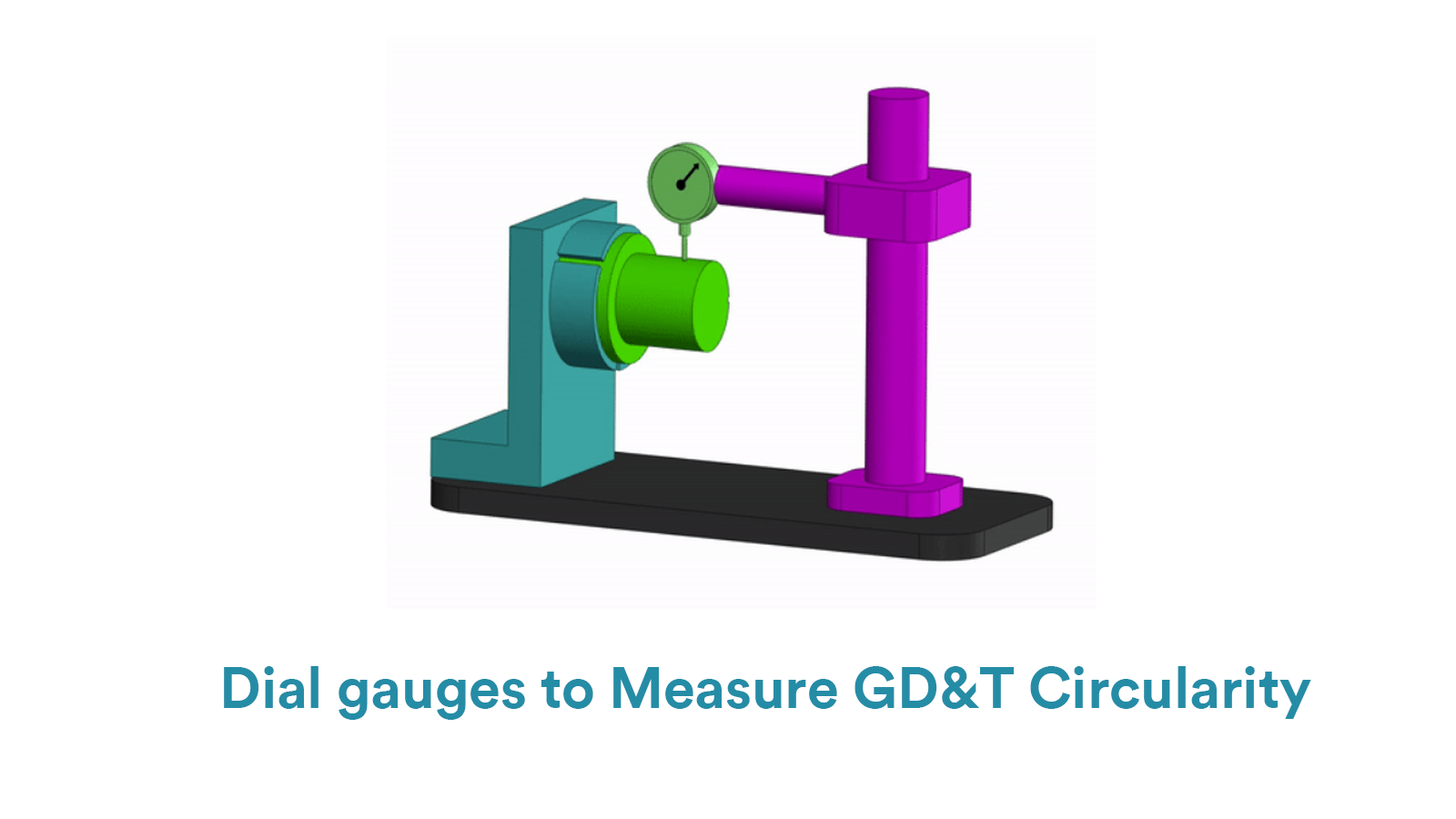
Compared with height gauges, using CMMs to measure circularity is more efficient and accurate, suitable for high-accuracy measuring requirements. The operating steps are as follows:
Firstly, calibrate the CMM and fix the measured feature.
Secondly, select the crucial cross-section to measure and establish the coordinate system.
Finally, use CMM software to calculate the deviation.
Calipers are simple tools to measure circularity, suitable for low-accuracy rough inspection. They can’t detect form deviation like waviness and taper. The steps are simple: measure diameters at different cross-sections and multiple axial points, then calculate the difference between the maximum and minimum values.

Straightness is to confine the deviation from a line of the truly manufactured features to an ideal theoretical line.

Flatness controls the applicable form deviation from the true surface to the ideally designed surface.

A datum is a theoretically ideal point, axis, or plane which is derived from the true geometric counterpart of a specified datum feature.

Cylindricity is to control the overall deviation of a cylindrical surface from a perfect geometric cylinder.