How Does a CNC Turning Machine Work?
The operation process of the CNC turning center can be divided into 4 parts. They are designing the CAD model, converting the CAD file to a CNC program or pre-programming, preparing a CNC machine, and executing the machining operation, i.e., material cutting itself.
Designing the CAD Model
The acronym CAD implies Computer-Aided Design. It is intended to create a 2D vector or 3D solid part design of an object enabling a CNC machine to produce a model with the necessary technical specifications.
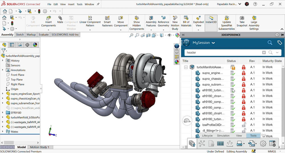
CAD software automatically performs complex geometrical calculations while creating a realistic model, as shown in the image below.
CAD modeling assists in creating a virtual reality object that has the same properties as a physical object. Some of the properties that can be considered include material, weight, size, optical and psychical ones, and others.
After a CAD design is complete, it should be exported to a CNC-compatible file format, for example, STEP and IGES.
Then, it is necessary to convert a CAD file into an actual CNC program; a CNC turning machine works by which.
Pre-Programming
In CNC turning, pre-programmed CAD software installed on a computer connected to a CNC turning center dictates the movement of the machine’s axis. To be executed, instructions to the turning machine must be coded using means of G-code and M-code programming.
Numerous software solutions enable the transfer of a CAD file into a CNC file, including CAD programs with this option. The basics is that all of them use a programming language known as G and M code programming. It enables activating a CNC machine’s programmable logic controller and executes the intended function.
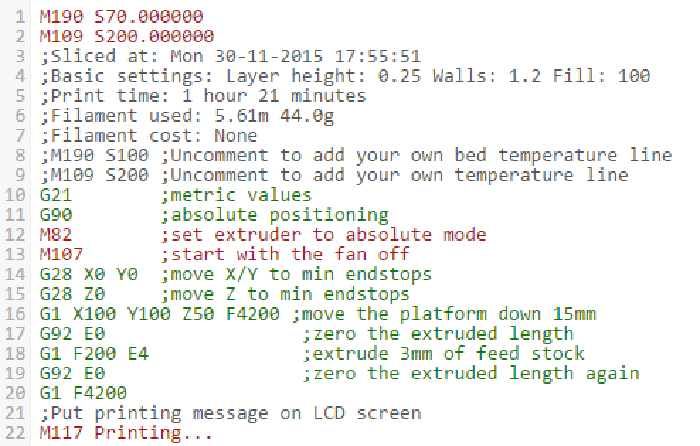
An example of a CNC program that has an integrated CAD file is shown in the image below.

G-code
This software programming language is used to control a CNC machine directly. Its function is to command a CNC turning machine to change the geometric coordination of its tools’ axes.
G-code is a set of instructions and looks like a letter “G” followed by a number. For instance, “G00” means a rapid, non-cutting move. Another part of the G-code is commanding a center to change the geometric coordinates. It looks like the name of an axis, for instance, “X” followed by a number meaning a distance, for instance, “-80”. Such instruction to a CNC turning machine implies moving -80 mm on the X-axis.
M-code
M-code is a complementary part of G-code and is responsible for non-geometry machine functions. Examples are spindle rotation start and stop, pallet change, flood coolant on and off, and others.
All the existing commands to a CNC turning machine can be coded using the described programming language, as shown in the image below.
A CNC turning center must have a well-coded program to construct a component that is exactly the same as the previously designed 3D CAD object.
Preparation of a CNC Turning Machine
In CNC milling, the preparation of a piece of machinery that executes the function can be roughly divided into two stages. These parts are adjustment of settings and choosing and attaching the required tooling.
Adjustment of Settings
The properties of a material selected are used to determine the setting of the mode they are to be machined at. It is explained with the possibility for a material to be cracked, chipped, partially melted, or deteriorated in any other way if settings are not appropriate.
The following CNC turning machine settings should be adjusted for every distinct material.
- Cutting speed. This parameter refers to how a CNC turning center’s tooling removes material from a workpiece. It is measured in surface feet per minute (SFPM or SFM).
- Cutting feed rate. In other words, it is how fast the workpiece is fed toward the machine tool. It is measured in inches per minute (IPM).
- Depth of cut. It implies how deep a CNC turning center’s tooling cuts into the workpiece. It is also measured in inches per minute (IPM).
Along with adjusting settings, adjustment of cutting tools should also be implemented.
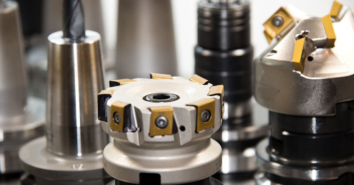
Adjustment of Tooling
Ensuring that the set of cutting tools installed is sufficient for a particular component manufactured is vital. Without this stage, a program cannot be executed correctly, and it should be done before changing material and design.
As exemplified previously, CNC turning machines are more advanced than a lathe and can perform functions genuinely attributed to milling machines. The examples of tooling used for specific purposes in CNC turning centers are the following.
- CNC drilling equipment. It includes rotating drill bits to produce cylindrical holes. Types of drill bits are spotting drills (shallow or pilot holes) and peck drills (reduction of the number of chips). The other existing forms of drills are screw machine drills (holes without a pilot hole) and chucking reamers (enlarging previously produced holes).
- CNC Turning equipment. It includes rotating multipoint cutting tools for shaping. Types of such cutting equipment are a chamfering tool (creating a bevel or furrow) and a knurling tool (creating or pressing a pattern onto a round section). The other existing turning tools are facing tools (cutting flat surfaces perpendicularly) and grooving tools (slot cutting).
Besides choosing the appropriate types of equipment, tooling parameters such as size, diameter, and material it is made of, should also be paid attention to.
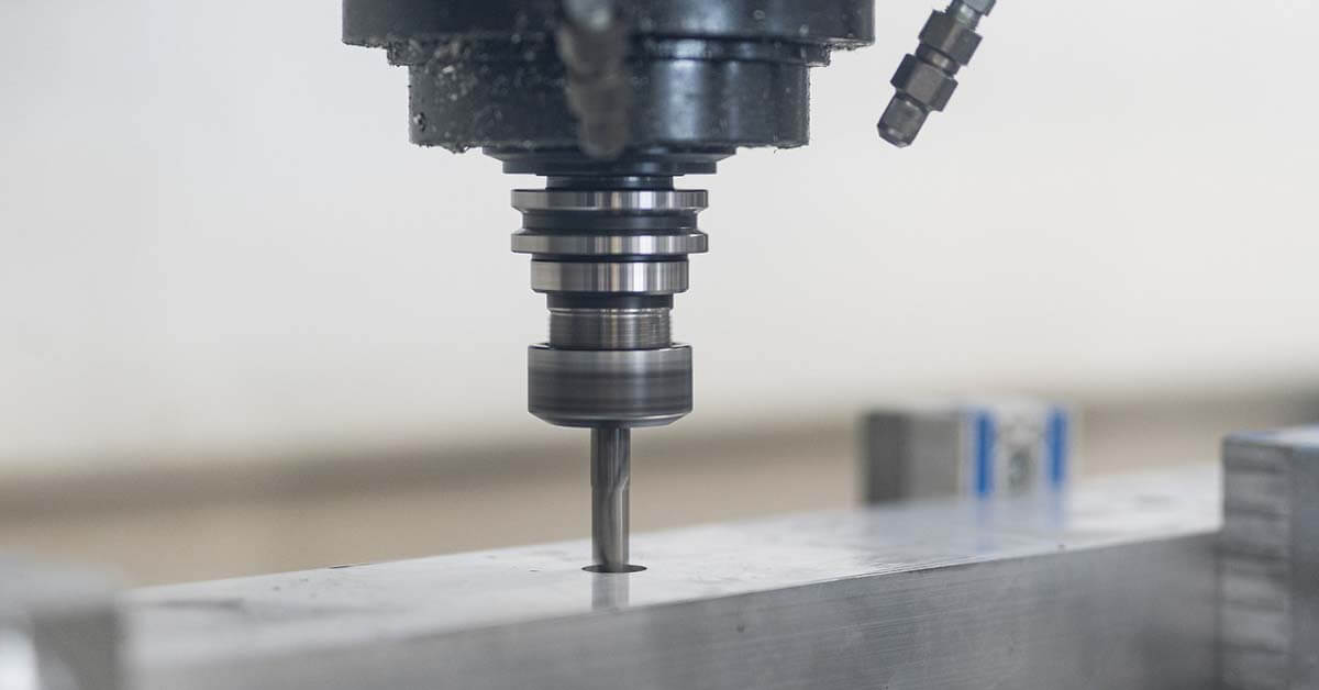
Machining Operation
Removing material from a workpiece is the primary function of a CNC turning machine, intended to produce components with high precision.
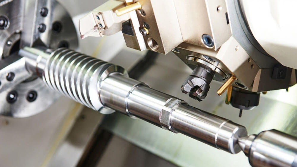
The general principle of turning can be described as holding a workpiece in a chick and rotating while a tool is being fed to the workpiece. Thus, it creates the desired shape and is called subtracting machining.
The moving section of a CNC turning center, which is called the spindle, includes the cutter and moves along the axis of the machined part while it is being rotated. The workpiece is fixed and positioned in a linear direction to the spindle.
Machining operations a CNC turning machine can perform include the following:
- Contour turning. Forming a contoured form in the turned part.
- Taper turning. Creating a tapered cylinder or conical shape.
- Chamfering. Cutting an angle of the cylinder to form a “chamfer.”
- Facing. Creating a flat surface on the face of the workpiece.
- Form turning. Plunging a tool radially into the workpiece.
- Boring. Feeding a single-point tool linearly on the inside diameter of an existing hole in a workpiece.
- Drilling and Reaming. Feeding a drill/reamer into the rotating workpiece along its axis.
- Grooving/Cut-off. Feeding a toll radially to a rotating workpiece to groove or to cut off the end of a part (parting).
- Threading. Feeding a pointed tool linearly across the outside surface of a rotating workpiece parallel to the axis.
- Knurling. Producing a regular cross-hatched pattern in the workpiece’s surface.
A CNC turning center is a highly versatile piece of machinery capable of implementing multiple operations to shape the material into a designed object.
What are the Main Components of a CNC Turning Machine?
The CNC turning machine is a complex center consisting of parts, outlined in the image below and listed further in the text.

1. Machine bed. It is also known as the main base for a CNC turning center on which the other components are mounted.
2. Headstock. Located on the machine’s left side, this wall-holding device includes the master spindle connected to servo motors utilized as spindle drivers.
3. Sub-spindle. It is separated from the main one and intended to fulfill complementary cutting functions.
4. Tailstock. It supports the workpiece axially and can be adjusted along the length axis.
5. Chuck. This three-jaw hydraulic part is the workpiece holding device.
6. Tool turret. This part enables the change of the cutting tools required for machining.
7. Guideway. This device enables the tool to move horizontally or vertically.