When an inclined feature of a component needs to be controlled, the angularity GD&T comes into play. In this part, we will further explain its definition, tolerance zone and callout.
As one of the orientation tolerances in GD&T Symbols, angularity GD&T is used to control a particular angle between the specified feature and the datum feature, which will hugely influencing assembly accuracy.
Angularity GD&T can be used to control the angular relationship between a specified line to a reference line, but it is more commonly applied to maintain a surface at a specific angle to a datum plane.
When used in a feature of size, it controls the central axis of the feature. What’s more, it can also be used to control the derived median plan of a non-circular feature like a tab or a slot.
According to the controlled element of angularity GD&T, it is easy to misunderstand that the tolerance zone of angularity GD&T would directly refine the angle like 60°+/-5’, which means that the tolerance zone would be a sector zone, and the controlled feature should be at 60° with the datum, allowed to deviate from 3’ on either side.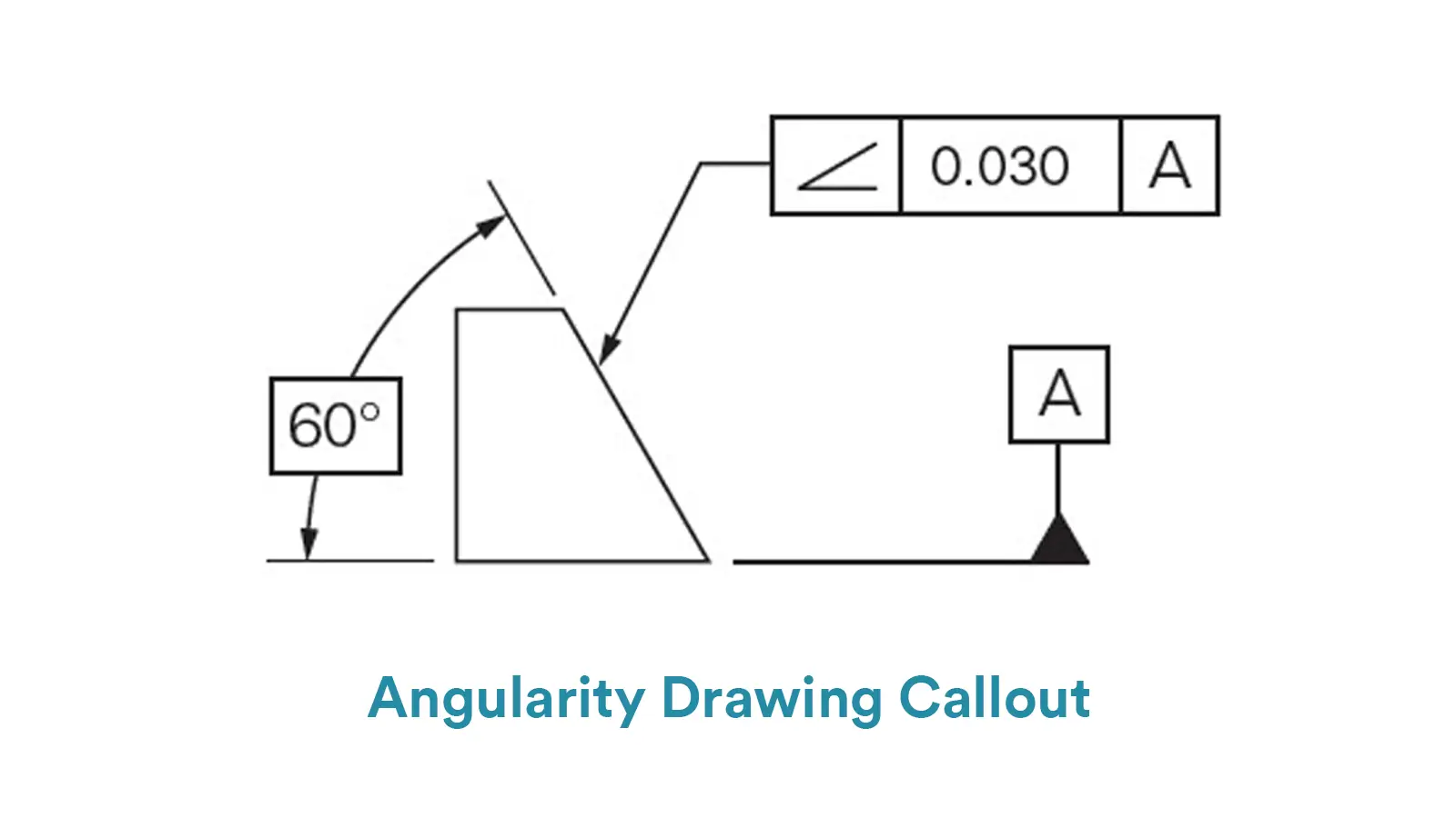
However, the specified angle is indirectly controlled by the tolerance zone of angularity GD&T.
For surface angularity, the tolerance zone consists of two parallel planes that are both at a specific angle with the datum surface. All points on the measured surface are demanded to lie within these two planes.
And the tolerance value, the permissible deviation, is the perpendicular distance between the two parallel planes.
That is to say, the allowed deviation of surface angularity is indirectly controlled by the distance of the tolerance zone instead directly by angular changing, which is same as surface parallelism and surface perpendicularity.
In short, surface angularity does not directly control the angular variation of the measured surface, but controls the envelope where the entire surface must lie within.
For axis angularity, the tolerance zone is a cylindrical zone whose center axis is at exact specified angle with the datum. All points on the measured axis should lie within this cylinder and the accepted angular deviation is controlled by shortening or lengthening the diameter of this cylinder.
And note that though the tolerance value is the diameter of the cylindrical tolerance zone, the max deviation of the measured axis would be only half of the diameter.
For surface angularity, the feature control frame is composed with three elements.
The first element is the GD&T symbol of angularity, which is an acute angle opening to the right.
The second element is the tolerance value of GD&T angularity, which is the distance of the two parallel planes that form the tolerance zone of surface angularity.
And the third element is the datum that the measured surface is supposed to refer to.
Then the feature control frame is directly leaded to the measured surface with a pointing arrow, or is connected with an extension line of the measure surface to indirectly show the controlling relation.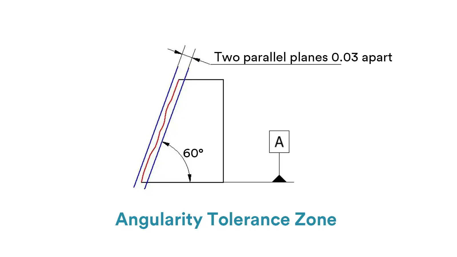
For axis angularity, the feature control frame is also comprised of three elements, with main difference in the second subsection from surface angularity.
Similar to surface angularity, the GD&T symbol of angularity is also the first element of axis angularity’s feature control frame. While the composition of second part is much different.
As the tolerance zone of axis angularity is a cylinder and the tolerance value is its diameter, the second part mainly includes the symbol of diameter and the tolerance value itself. Symbols of material modifiers may appear in the second part, but it is not common.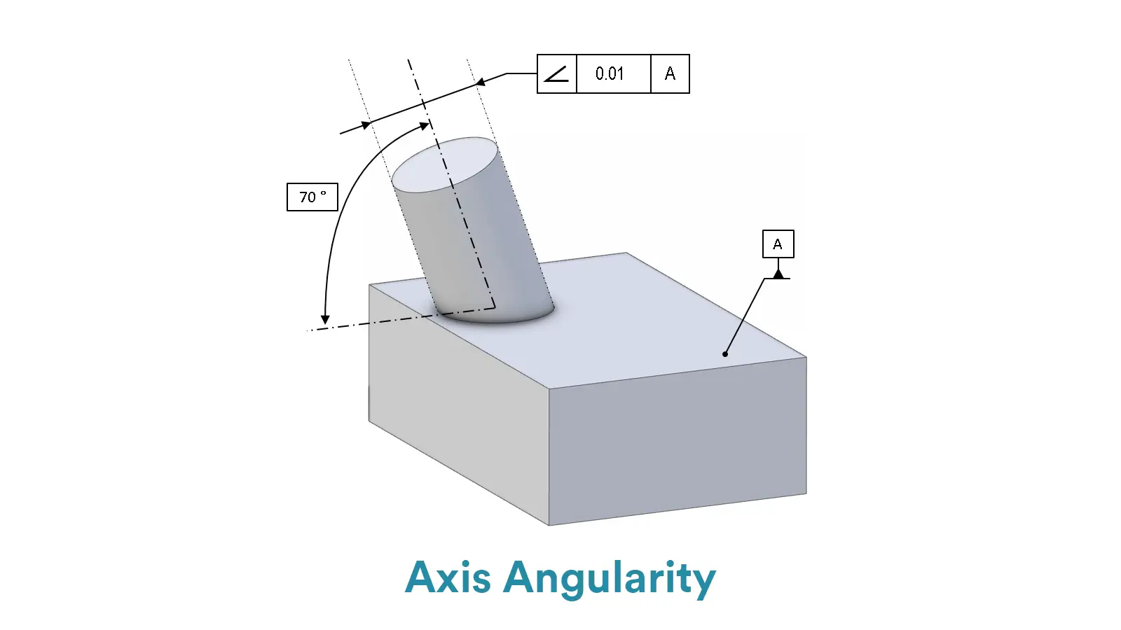
The third element is the datum axis or surface. The callout of axis angularity is usually shown by connecting the measured axis with the feature control frame leaded through a pointing arrow.
Note that the specified angle is not indicated in the feature control frame but is commonly shown as a basic angle on engineering drawings.
Just as that shown in mathematics, the basic angle in engineering drawings is also shown by a curve line with value of degree between a measured surface and the datum surface.
For measurement of angularity, you should know that it is measured actually through flatness measurement, since angularity actually maintains the flatness of a surface at a specified angle and the tolerance zone is made of parallel planes.
Here we will produce some common methods for angularity measurement with their pros and cons.
Using a sine bar with dial gauge is the traditionally simplest method for surface angularity measurement. For simple tools and low cost, this method is suitable for on-site measurement.
While the accuracy is certainly low due to manual operation and at the same time it takes much time to adjust angle. The step-by-step operation to measure angularity by this method is as follows: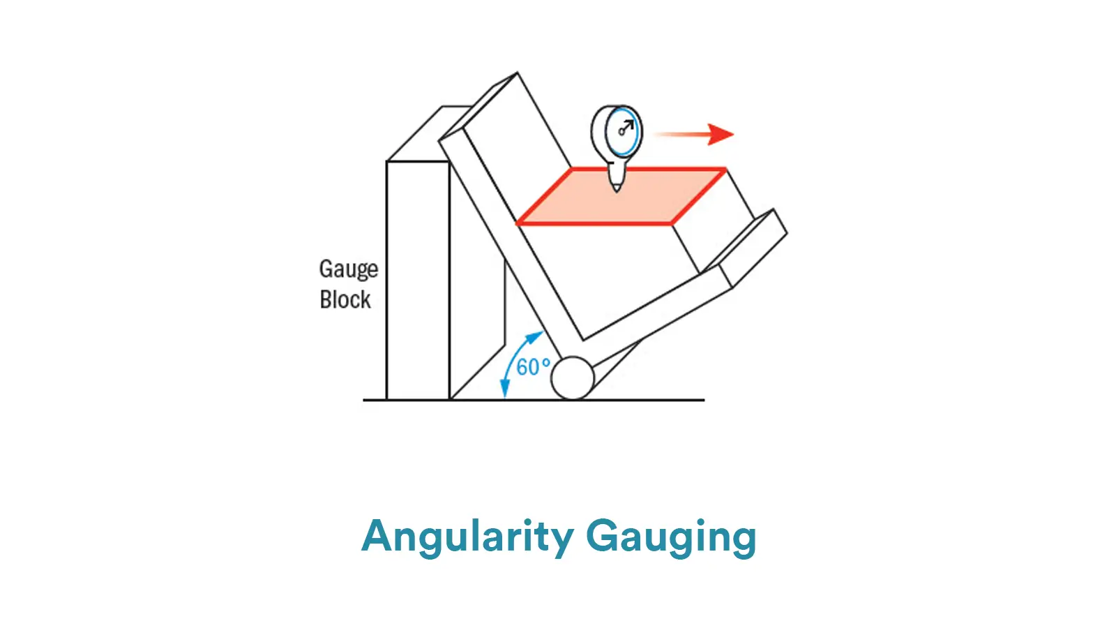
Firstly, fix the datum surface of the measured component on the sine bar and adjust to the theoretically specified angle by gauge blocks, causing the measured surface parallel to the granite slab.
Secondly, slide the dial gauge along the measured surface and record the reading data.
Thirdly, compare the difference between the max and min readings. If the difference does not fall outside the tolerance zone, the measured feature passes.
Coordinate measuring machines(CMMs) are high-end automate equipment that can measure various geometric features including surface angularity and axis angularity.
However, CMMs are disadvantage in high cost for both purchase and maintenance. And the equipment is sensitive to measuring environment. The step-by-step operation to measure angularity by this method is as follows:
Firstly, measure the datum feature with the CMM probe to establish the coordinate system(simulating a XY plane and setting a datum orientation).
Secondly, enter the design angle in the software and collect data of multiple points along the surface or axis.
Thirdly, fit the data and calculate the max deviation from the theoretical angle. And then calculate the linear deviation through particular formula by software. If the linear deviation is small than the tolerance value, the measured feature passes.
With high accuracy up to micrometer dimension, optical projectors are suitable to measure complex features or small components. And the non-contact measurement can prevent geometric deformation.
However, the equipment is disadvantage in high cost and sensation to environmental factors. The step-by-step operation to measure angularity by this method is as follows:
Firstly, fix the measured component on the platform and align the datum feature with the equipment’s coordinate system.
Secondly, set the theoretically specified angle based on the datum plane or axis. And then use the optical probe or laser to scan the measured surface and collect data of multiple points.
Thirdly, calculate the max deviation from the specified angle by software. If the value lie within the tolerance zone, the measured feature passes.

Cylindricity is to control the overall deviation of a cylindrical surface from a perfect geometric cylinder.

Parallelism GD&T is to ensure that the reference surface or axis is parallel to the datum surface or axis.

Perpendicularity GD&T is used to control the measured surface or axis, keeping 90° with the datum surface or axis.

GD&T angularity GD&T is used to control a particular angle between the specified feature and the datum feature