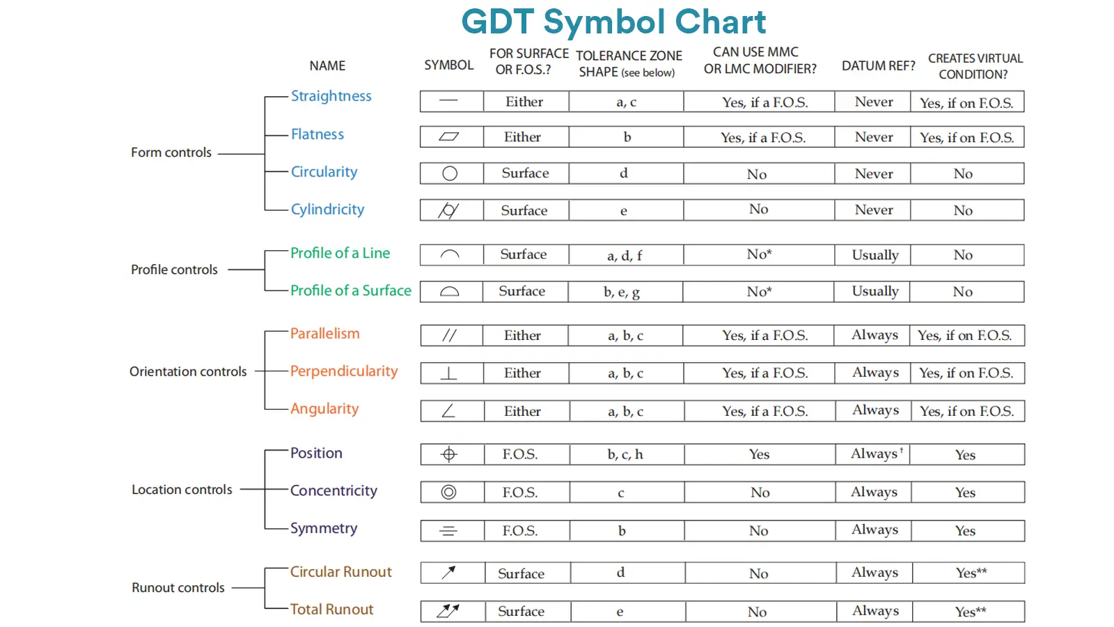
Straightness is to confine the deviation from a line of the truly manufactured features to an ideal theoretical line.

Flatness controls the applicable form deviation from the true surface to the ideally designed surface.

A datum is a theoretically ideal point, axis, or plane which is derived from the true geometric counterpart of a specified datum feature.

GD&T circularity is mainly used to control the deviation level from the actual circular profile to the ideally perfect circle.
Straightness is to confine the deviation from a line of the truly manufactured features to an ideal theoretical line.
Flatness controls the applicable form deviation from the true surface to the ideally designed surface.
A datum is a theoretically ideal point, axis, or plane which is derived from the true geometric counterpart of a specified datum feature.
GD&T circularity is mainly used to control the deviation level from the actual circular profile to the ideally perfect circle.

Cylindricity is to control the overall deviation of a cylindrical surface from a perfect geometric cylinder.

Parallelism GD&T is to ensure that the reference surface or axis is parallel to the datum surface or axis.

Perpendicularity GD&T is used to control the measured surface or axis, keeping 90° with the datum surface or axis.

GD&T angularity GD&T is used to control a particular angle between the specified feature and the datum feature

GD&T profile of a line is to control the deviation of any actual linear element on surfaces, like straight lines, curved lines or lines on cross-section planes from their exactly ideal profile.

Symmetry controls that the Median Plane of a non-rotating feature must be aligned with the Datum Center Plane. It has been removed from the standard GD&T toolbox.

Concentricity is a position tolerance that measures the degree to which the center points of circular features (cylinders, cones, spheres) coincide relative to a shared datum axis or point.

True position GD&T is one of the position symbols in GD&T that is used to control the positional accuracy of a feature of size, such as a hole, shaft or slot, with respect to the datum coordinate system.

Free state symbol indicates that a specific dimensional tolerance or geometric tolerance is applied to a part at its free state.

It refers to the requirement for dimensional and geometric tolerance inspection of parts under controlled external constraints.

Circular runout GD&T is a geometric tolerance used to control the variation of a part’s circular profile as it rotates 360° around the datum axis.

Total runout is one of the runout symbols that mainly controls the runout deviation of the measured feature’s entire surface during rotation around the datum axis.

LMC is a feature of size symbol which refers to the dimensional condition where the particular feature contains the least amount of material within its indicated tolerance.

MMC is a feature of size symbol which refers to the dimensional condition where the particular feature contains the maximum amount of material within its indicated tolerance.

Radius specifies the distance from a circle’s center to its circumference, fundamentally defining the circle’s size and shape.

Spherical Radius (SR) is defined as the radial distance extending from a sphere’s geometric center to any point on its circumferential surface.

Controlled Radius is a specific type of radius control that requires an arc feature to have a smooth profile with no reverse curvature.

GD&T Independency Symbol is used to refine geometric control beyond the default envelope principle(Rule #1).

The GD&T slope modifying symbol is used in engineering drawings to control the slope or “flat taper” of a feature.

Conical taper symbol is applied to define the agnel of a conical surface. Conical taper refers to the ratio of the diameter change to the length change

In Geometric Dimensioning and Tolerancing, the envelope requirement defines that the form of a feature of size is controlled by its limits of size.

Unequally disposed profile is one GD&T profile symbol whose tolerance zone is asymmetrically disposed around the ideal profile of a feature.

Continuous feature GD&T is used to indicate that multiple adjacent geometric features should be served as a single continuous feature.

Dimension origin clarifies the datum for dimensional measurement, ensures consistent understanding of part dimensions.

GD&T projected tolerance zone defines a tolerance zone that extends beyond the physical boundary of a feature.

The arc length symbol is used to state a dimension value indicated on the engineering drawing refers to the length of an arc on a curved outline.

Depth refers to the vertical distance from a datum or feature surface to another feature surface, usually an internal or recessed feature.

It indicates the specific conditions and tolerances of a geometric control to a particular feature on a part.