Table of Contents
GD&T (Geometric Dimensioning and Tolerancing) is an internationally standardized engineering language, following standards such as ASME Y14.5 or ISO 1101.
Whether in China, Germany, or the United States, as long as individuals can understand GD&T drawings, they can manufacture and inspect parts based on the same document, ensuring consistency and interchangeability of parts produced globally.
As members of the CNC industry, designers, programmers, machine operators, and QC inspectors must have a deep understanding of GD&T symbols to achieve precise, clear, and unambiguous communication.
Key Takeaways:
GD&T is an internationally standardized engineering language (following ASME Y14.5 or ISO 1101). GDT tolerance is one part of CNC machining tolerances.
GDT’s primary purpose is to ensure consistency, interchangeability, and precise communication of parts globally by allowing manufacturers and inspectors to work from the same drawing.
GDT are classified into Form Tolerances, Profile Tolerances, Orientation Tolerances, Location Tolerances and Runout Tolerances.


1. GD&T Symbols Classification
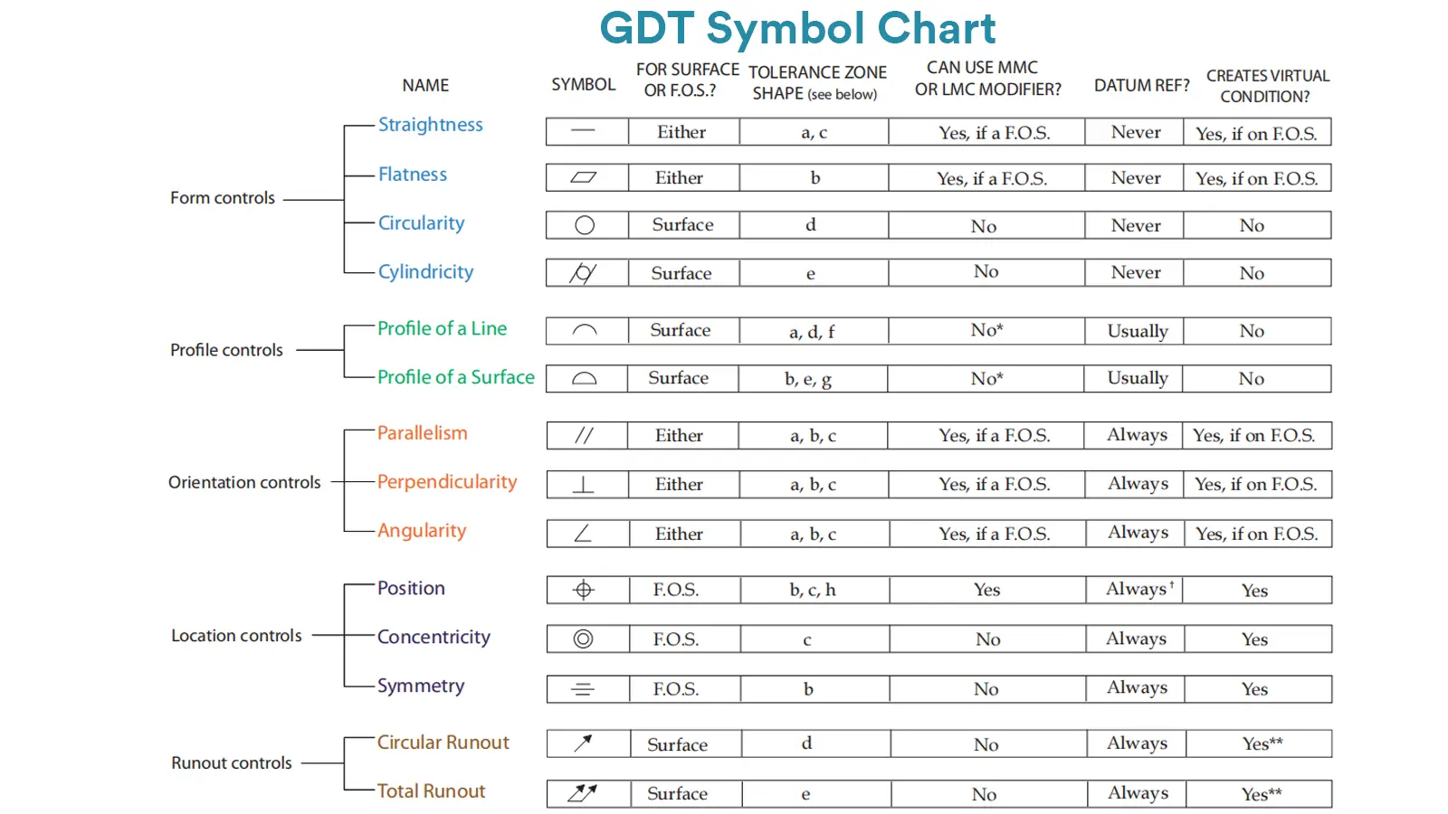
The image above is the GD&T symbols Chart. According to functions and purposes, GD&T symbols are categorized as below.
1.1. Form Tolerances
These symbols are used to control the geometric shape of parts, including:
Straightness: Controls the straightness of a line.
Flatness: Controls the flatness of a surface or part.
Roundness: Controls the roundness of circular features.
Cylindricity: Controls the cylindricity of cylindrical features.
1.2. Profile Tolerances
These symbols are used to control the shape and location of curves or surfaces:
Profile of a Line: Controls the shape of a curve.
Profile of a Surface: Controls the shape and position of a surface in space.
1.3. Orientation Tolerances
These symbols are used to control the orientation of part features, including:
Parallelism: Controls the parallel relationship between two lines or surfaces.
Perpendicularity: Controls the perpendicular relationship between a line or surface and a datum.
Angularity: Controls the angular relationship between two lines or surfaces.
1.4. Location Tolerances
These symbols are used to control the position of part features, including:
Position: Controls the precise position of holes or other features relative to a datum.
Concentricity: Controls whether two circular features (e.g., holes and shafts) are coaxial.
Symmetry: Controls the symmetry of two features relative to a datum plane.
1.5. Runout Tolerances
These symbols are used to control the amount of runout (or wobble) of a part during rotation, ensuring the part’s rotational accuracy:
Total Runout: Controls the runout of the entire part or feature during rotation.
Circular Runout: Controls the local circular runout of a part or feature during rotation.
1.6. Surface Finish Symbols
These symbols are used to specify the surface roughness requirements of parts, including:
Ra (Arithmetic Average Roughness): A common surface roughness unit, indicating the microscopic unevenness of the surface.
Rz (Ten-Point Height Roughness): Represents the maximum height of the surface irregularities.
1.7. Size Tolerances
These symbols are used to control the dimensional tolerances of parts, indicating the allowable dimensional variation:
Linear Dimension Tolerances: Defines the tolerances for linear dimensions such as length, width, and height of parts.
Geometrical Dimension Tolerances: Defines the tolerances for features like hole diameters and shaft diameters.
1.8. Datum Symbols
Datum symbols are used to mark the reference points, lines, or planes for processing and measurement of parts:
Datum: Represents the reference point, line, or surface used for processing or measurement.
1.9. Strength and Assembly Symbols
These symbols are used to indicate special requirements for parts during assembly:
Assembly Tolerances: Defines the tolerances for the relative position of parts during assembly.
Shear Strength: Indicates the strength requirements of the part.
1.10. Other Special Symbols
There are also special symbols used for other specific requirements, such as:
Welding Symbols: Indicate the welding process required for a part.
Heat Treatment Symbols: Indicate the heat treatment requirements for a part.
2. The Importance of GD&T Symbols
Understanding the GD&T Symbols is very important.
2.1. GD&T is the “Precise Instruction” for CNC Programming and Machining
CNC programmers need to write tool paths (G-codes) based on engineering drawings. GD&T provides much deeper information than simple dimensional tolerances.
GD&T drawings clearly specify datums (such as Datum A, B, C). Programmers must understand these datums to correctly set up the part coordinate system and plan the machining sequence.
2.2. GD&T Enables “First-Time-Right” CNC Machining, Maximizing Efficiency
Programmers and operators who don’t understand GD&T may resort to “over-machining” out of fear of exceeding tolerances.
A programmer familiar with GD&T understands that a ⌀0.2 position tolerance offers a larger allowable area than a ±0.1mm linear tolerance (round vs. square).
By fully utilizing this entire area in programming, they can select more aggressive and efficient machining parameters while ensuring the part is 100% compliant.
2.3. GD&T Ensures Part Functionality and Interchangeability
Many parts need to fit together (e.g., shafts and holes, gears and gears), slide, or rotate. GD&T allows you to directly define the geometric features affecting functionality (such as flatness, perpendicularity, and concentricity), rather than just size.
2.4. GD&T Provides Clear Inspection Guidelines for Quality Control
After CNC machining, parts need to be inspected. GD&T drawings are the “answer sheet” for the inspection department. CMM (Coordinate Measuring Machine) operators must fully understand the GD&T symbols on the drawings to write accurate inspection programs.
2.5. Facilitates Efficient Communication Between Design and Manufacturing
CNC workshops often need to communicate with design engineers. Using GD&T as a shared language significantly reduces misunderstandings and disputes.
When CNC engineers see GD&T symbols on a drawing, they immediately understand the part’s functionality. For example, a surface with strict flatness requirements indicates the need for a good seal or fit.
A hole with a maximum material condition (M) symbol indicates the hole is allowed tolerance compensation when mated with a pin.
Manufacturing engineers familiar with GD&T can review drawings and offer constructive suggestions.
For instance, suggesting that a feature be controlled by a profile tolerance rather than separately marking angles and positions could maintain functionality while providing greater machining flexibility, reducing costs.
2.6. GD&T Reduces Scrap Rate and Saving Costs
Misunderstanding drawings is one of the main reasons for part scrapping. Understanding GD&T symbols reduces scrap rates, saves costs, and generates significant business benefits.
GD&T eliminates the ambiguity of traditional dimensional tolerances, ensuring that the definition of “conformance” is unique and clear throughout the entire process from design to machining to inspection.
Misunderstanding datum sequences or modifiers (such as M or L circles) could result in scrapping an entire batch of parts, causing substantial material and labor losses. Understanding GD&T is the most effective safeguard against such errors.
3. Learn Specific GD&T Symbols
To help readers better understand each GD&T symbol, click on the icons below to access detailed explanations of each symbol.
Lucas is a technical writer at ECOREPRAP. He has eight years of CNC programming and operating experience, including five-axis programming. He also spent three years in CNC engineering, quoting, design, and project management. Lucas holds an associate degree in mold design and has self-taught knowledge in materials science. He’s a lifelong learner who loves sharing his expertise.

GD&T Straightness
Straightness is to confine the deviation from a line of the truly manufactured features to an ideal theoretical line.

GD&T Flatness
Flatness controls the applicable form deviation from the true surface to the ideally designed surface.

Datum GD&T
A datum is a theoretically ideal point, axis, or plane which is derived from the true geometric counterpart of a specified datum feature.

GD&T Circularity
GD&T circularity is mainly used to control the deviation level from the actual circular profile to the ideally perfect circle.

GD&T Straightness
Straightness is to confine the deviation from a line of the truly manufactured features to an ideal theoretical line.

GD&T Flatness
Flatness controls the applicable form deviation from the true surface to the ideally designed surface.

Datum GD&T
A datum is a theoretically ideal point, axis, or plane which is derived from the true geometric counterpart of a specified datum feature.

GD&T Circularity
GD&T circularity is mainly used to control the deviation level from the actual circular profile to the ideally perfect circle.

GD&T Cylindricity
Cylindricity is to control the overall deviation of a cylindrical surface from a perfect geometric cylinder.

GD&T Parallelism
Parallelism GD&T is to ensure that the reference surface or axis is parallel to the datum surface or axis.

Perpendicularity
Perpendicularity GD&T is used to control the measured surface or axis, keeping 90° with the datum surface or axis.

GD&T Angularity
GD&T angularity GD&T is used to control a particular angle between the specified feature and the datum feature

Profile of a Line
GD&T profile of a line is to control the deviation of any actual linear element on surfaces, like straight lines, curved lines or lines on cross-section planes from their exactly ideal profile.

GD&T Symmetry
Symmetry controls that the Median Plane of a non-rotating feature must be aligned with the Datum Center Plane. It has been removed from the standard GD&T toolbox.

GD&T Concentricity
Concentricity is a position tolerance that measures the degree to which the center points of circular features (cylinders, cones, spheres) coincide relative to a shared datum axis or point.

GD&T True Position
True position GD&T is one of the position symbols in GD&T that is used to control the positional accuracy of a feature of size, such as a hole, shaft or slot, with respect to the datum coordinate system.

Free State Symbol
Free state symbol indicates that a specific dimensional tolerance or geometric tolerance is applied to a part at its free state.

Restrained Condition
It refers to the requirement for dimensional and geometric tolerance inspection of parts under controlled external constraints.

Circular Runout
Circular runout GD&T is a geometric tolerance used to control the variation of a part’s circular profile as it rotates 360° around the datum axis.

Total Runout
Total runout is one of the runout symbols that mainly controls the runout deviation of the measured feature’s entire surface during rotation around the datum axis.

LMC
LMC is a feature of size symbol which refers to the dimensional condition where the particular feature contains the least amount of material within its indicated tolerance.

MMC
MMC is a feature of size symbol which refers to the dimensional condition where the particular feature contains the maximum amount of material within its indicated tolerance.

Radius
Radius specifies the distance from a circle’s center to its circumference, fundamentally defining the circle’s size and shape.

Spherical Radius
Spherical Radius (SR) is defined as the radial distance extending from a sphere’s geometric center to any point on its circumferential surface.

Controlled Radius
Controlled Radius is a specific type of radius control that requires an arc feature to have a smooth profile with no reverse curvature.

GD&T Independency
GD&T Independency Symbol is used to refine geometric control beyond the default envelope principle(Rule #1).

Slope Modifying
The GD&T slope modifying symbol is used in engineering drawings to control the slope or “flat taper” of a feature.

Conical Taper
Conical taper symbol is applied to define the agnel of a conical surface. Conical taper refers to the ratio of the diameter change to the length change

Envelope
In Geometric Dimensioning and Tolerancing, the envelope requirement defines that the form of a feature of size is controlled by its limits of size.

Unequally Disposed
Unequally disposed profile is one GD&T profile symbol whose tolerance zone is asymmetrically disposed around the ideal profile of a feature.

Continuous Feature
Continuous feature GD&T is used to indicate that multiple adjacent geometric features should be served as a single continuous feature.

Dimension Origin
Dimension origin clarifies the datum for dimensional measurement, ensures consistent understanding of part dimensions.

Projected Tolerance Zone
GD&T projected tolerance zone defines a tolerance zone that extends beyond the physical boundary of a feature.

Arc Length
The arc length symbol is used to state a dimension value indicated on the engineering drawing refers to the length of an arc on a curved outline.

Depth
Depth refers to the vertical distance from a datum or feature surface to another feature surface, usually an internal or recessed feature.

Feature Control Frame
It indicates the specific conditions and tolerances of a geometric control to a particular feature on a part.


